® FAST ETHERLINKâ PARALLEL TASKINGâ 10/100BASE-T4 PCI NETWORK ADAPTER USER GUIDE A member of the 3Com Fast EtherLink family of adapters Part No.
3Com Corporation ■ 5400 Bayfront Plaza ■ Santa Clara, California ■ 95052-8145 © 3Com Corporation, 1996. All rights reserved. No part of this documentation may be reproduced in any form or by any means or used to make any derivative work (such as translation, transformation, or adaptation) without permission from 3Com Corporation.
LIFETIME WARRANTY ® 3Com’s EtherLinkâ, TokenLinkâ, Fast EtherLink, FDDILinkä, and 3Com Impactä ISDN ISA adapters have a Lifetime Warranty. To ensure the very best 3Com service and support, take the time to complete the product registration card.
Customers in the countries shown below should send the completed registration card to the appropriate address. Customers in other non-U.S. locations should send the registration card to the U.S. address on the front of the card. ■ Asia ■ 3Com Asia Ltd., Marketing Department Room 2506-07, 25/F.
CONTENTS ABOUT THIS GUIDE Introduction 1 How to Use This Guide Conventions 2 1 1 INTRODUCTION Adapter Features 1-3 PCI Technology 1-4 2 INSTALLING THE ADAPTER Inspecting the Adapter 2-1 Installing the Boot PROM 2-2 Installing the Adapter 2-2 Connecting to the Network 2-3 3 LOADING THE NETWORK DRIVERS Summary of Driver Loading Procedures 3-1 Using the EtherDisk Diskette 3-2 Accessing DOS 3-2 Using Windows 95 3-3 Confirming Adapter Installation for Windows 95 Using NetWare ODI 3-5 One Adapter in a Client
Loading NDIS Drivers 3-11 Updating NDIS Drivers 3-12 Auto Select Media Type 3-12 Transcend PC Link SmartAgent Driver Agents Desktop Management Interface 3-13 3-13 4 PERFORMING TROUBLESHOOTING AND DIAGNOSTIC TESTS Troubleshooting with the Diagnostic Tests Before Running the Tests 4-2 Types of Tests 4-2 Starting the Diagnostic Program 4-3 Running the Group 1 Tests 4-3 Running the Group 3 Test 4-4 Setting Up an Echo Server 4-5 Starting the Group 3 Test 4-6 Getting Help If a Test Fails 4-7 Changing the Test S
C SPECIFICATIONS Adapter Specifications C-1 Network Interface C-1 Physical Dimensions C-1 Environmental Operating Range Power Requirements C-1 C-1 D TECHNICAL SUPPORT On-line Technical Services D-1 3Com Bulletin Board Service D-1 Access by Modem D-1 Access by ISDN D-2 World Wide Web Site D-2 3ComForum on CompuServe D-2 3ComFacts Automated Fax Service D-3 Support from Your Network Supplier D-3 Returning Products for Repair D-4 GLOSSARY INDEX LIMITED WARRANTY FCC CLASS B CERTIFICATION CISPR B COMPLIANCE CE
FIGURES 1-1 10/100BASE-T4 PCI Adapter 1-2 2-1 PCI Computer with PCI and EISA Slots 2-2 Connecting Twisted-Pair Cable 2-4 3-1 AutoLink Information Screen 3-2 Main Menu 3-7 2-3 3-7 A-1 RJ-45 Connector Pin Assignments A-6 B-1 Multiple Adapter Option Configuration B-2 Changing Adapter Options B-4 B-3
TABLES 1 Text Conventions 2 Notice Icons 2 2 3-1 Summary of Driver Loading Procedures 3-1 3-2 Accessing DOS from Other Operating Systems 3-3 4-1 Adapter and Diagnostic Program Names (10 Mbps Adapter Only) 4-6 4-2 Fast EtherLink 10/100BASE-T4 PCI Adapter LEDs 4-10 B-1 Option Settings B-2
ABOUT THIS GUIDE Introduction This guide explains how to install the 3Comâ Fast EtherLinkâ Parallel Taskingâ 10/100BASE-T4 PCI adapter. Also included is information about loading drivers, troubleshooting the adapter, and using the diagnostic tests if a malfunction occurs. How to Use This Guide The following table shows where to find specific information in this guide.
2 ABOUT THIS GUIDE Conventions The following tables list text and icon conventions that are used throughout this guide: Table 1 Text Conventions Convention Description This typeface is used to represent displays that appear on Text represented as screen display your terminal screen, for example: NetLogin: Text represented as commands This typeface is used to represent commands that you enter, for example: print autolink.
1 INTRODUCTION The 3Comâ Fast EtherLinkâ Parallel Taskingâ 10/100BASE-T4 PCI adapter is a 32-bit adapter for use in a personal computer with a Peripheral Component Interconnect (PCI) computer bus. It operates whether or not bus mastering is enabled. This adapter (model number 3C595-T4) is a dual-speed adapter that can be connected to an Ethernet or Fast Ethernet network with a single connection over unshielded twisted-pair (UTP) cable.
1-2 CHAPTER 1: INTRODUCTION The 10/100BASE-T4 PCI adapter connects your PCI-compliant personal computer to an Ethernet network wired with IEEE 802.3 standard 10BASE-T or 100BASE-T4 twisted-pair cable. For information on the IEEE 802.3 standard as it relates to twisted-pair cable, refer to Appendix A. The adapter interoperates with all 10BASE-T products and all 10/100 T4 adapters and hub products. It is compatible with 3Com’s SNMP network management software (Transcendâ WorkGroup Manager).
Adapter Features 1-3 Check the documentation provided with the PCI computer to locate the bus master slots.
1-4 CHAPTER 1: INTRODUCTION PCI Technology The PCI local bus is a high-performance bus that provides a processor-independent data path between the CPU in a PC and high-speed peripherals. This interconnect mechanism is designed specifically to accommodate multiple highperformance peripheral devices that support networking and disk subsystems, graphics, full-motion video, and multimedia. The PCI specification defines two types of PCI devices: a target and a master.
2 INSTALLING THE ADAPTER This chapter discuses the following topics: ■ Inspecting the Fast EtherLink 10/100BASE-T4 PCI adapter ■ Installing the boot PROM ■ Inserting the adapter ■ Connecting to the network Inspecting the Adapter Before installing the adapter in your computer, you should visually inspect it for damage that might have occurred during shipment from the factory. CAUTION: Each adapter is packed in an antistatic container to protect it during shipment.
2-2 CHAPTER 2: INSTALLING THE ADAPTER 2 Verify that you have received all items listed in step 1, and inspect each item for damage. If you find any omissions or damage, contact your network supplier and the carrier that delivered the package. Installing the Boot PROM The boot PROM is optional and can be purchased separately. If you are installing it onto the adapter, follow the instructions that accompanied the boot PROM.
Connecting to the Network 2-3 EISA slot PCI slot Figure 2-1 PCI Computer with PCI and EISA Slots The adapter’s backplate should be flush with the computer’s chassis. Be sure that the adapter’s connector fingers are completely seated in the slot. 6 Replace the computer cover and reconnect all previously connected cables. Refer to the documentation provided by the computer’s manufacturer for details on installing expansion boards.
2-4 CHAPTER 2: INSTALLING THE ADAPTER For both 10BASE-T and 100BASE-T4 Ethernet networks, the Fast EtherLink PCI adapter uses Category 3, 4, or 5 unshielded twisted-pair (UTP) cable. Refer to Appendix A for more information on cabling. Figure 2-2 shows the backplate of an installed adapter with its RJ-45 connector.
Connecting to the Network 2-5 100BASE-T4 connections use all 4 pairs of wire normally contained in a bundle of Category 3, 4, or 5 UTP cable. The “straight through” connection should be made from the Fast EtherLink PCI adapter through the cable and connectors to the hub. No crossover in the cable is required. Refer to Appendix A for RJ-45 connector pin assignments.
3 LOADING THE NETWORK DRIVERS This chapter describes how to load the network drivers required to let the 3C595-T4 PCI adapter operate with your network operating system. This information is arranged according to the following topics: ■ Summary of driver loading procedures ■ Using the EtherDisk diskette ■ Accessing DOS ■ Loading network drivers Summary of Driver Loading Procedures Table 3-1 summarizes the driver loading procedures based on the network operating system running on your computer.
3-2 CHAPTER 3: LOADING THE NETWORK DRIVERS Using the EtherDisk Diskette The EtherDisk diskette contains the latest versions of the network drivers available when 3Com shipped the adapter. It also contains other important information concerning Fast EtherLink and EtherLink III adapters and their configuration. To obtain network operating system drivers not included on the EtherDisk diskette, contact the manufacturer of that network operating system or application.
Using Windows 95 3-3 installing the drivers. Table 3-2 provides the procedures to use to access DOS from various operating systems. Table 3-2 Accessing DOS from Other Operating Systems Operating System Procedure Windows 95 1 Turn on your computer. 2 Press [F8] as soon as you see this message: Starting Windows 95 3 Press [7], then press [Enter]. 4 Type install at the DOS command prompt to run the 3Com install program. OS/2 1 Boot your computer from a plain DOS diskette.
3-4 CHAPTER 3: LOADING THE NETWORK DRIVERS b In the panel at the bottom of the dialog box, type the drive name and pathname from which Windows 95 should copy the manufacturer’s files. (An information file on the diskette tells Windows 95 where to find the information it needs, for example A:\.) 5 Click OK. This imports the driver from the EtherDisk diskette.
Using NetWare ODI 3-5 6 Double-click the adapter name to display a description of the adapter and its current status. The next dialog box confirms that the adapter is working properly. 7 Click the Cancel button to leave each dialog box and return to the Control Panel.
3-6 CHAPTER 3: LOADING THE NETWORK DRIVERS AutoLink Installation To use the AutoLink program to install NetWare DOS ODI client software on a PC with a single adapter, follow these steps: 1 Make sure that you have booted the computer under DOS, version 3.1 or later, and that your computer is connected to the network, as detailed in Chapter 2. 2 Insert the EtherDisk diskette in a floppy drive on your computer and make that drive the active drive.
Using NetWare ODI 3-7 5 Read the screen and press [Enter]. 6 When the main menu screen shown in Figure 3-2 appears, select NetWare DOS ODI Client, and press [Enter]. EtherDisk-3C59X Fast EtherLink/EtherLink III Bus Master Adapter Family v.4.2 ESC=Cancel 3Com's auto installation software (AutoLink) automatically configures your adapter and workstation for use as a NetWare client. To use AutoLink: * Have only one 3Com Etherlink III PCI adapter installed * Use NetWare v2.X, v3.1X, or v4.
3-8 CHAPTER 3: LOADING THE NETWORK DRIVERS Auto installation may take a few moments. Several messages appear while the AutoLink program is running. A final message indicating successful installation appears. If you experience problems that occur only when using the AutoLink program, access the AUTOLINK.LOG file, as described in the section “Getting Help If a Test Fails” in Chapter 4. 7 When the auto installation process is finished, remove the diskette and reboot the computer.
Using NetWare ODI 3-9 4 When the AutoLink installation is complete, remove the diskette. 5 Turn off the computer, install the second adapter, and connect the network cable to the adapter. 6 Turn on the computer and access the C:\NWCLIENT subdirectory. 7 In the C:\NWCLIENT subdirectory access the NET.CFG file by typing: edit net.cfg 8 Scroll through the NET.CFG file to the LINK DRIVER 3C59X section.
3-10 CHAPTER 3: LOADING THE NETWORK DRIVERS 10 Repeat step 9 for any additional adapters that you may have installed. 11 Reboot the computer. Finding the Adapter’s Port Number When working in a NetWare environment with multiple adapters in a client computer, you must know each adapter’s port number. To find the adapter’s port number after inserting the adapters, follow these steps. 1 Access the main menu on the EtherDisk diskette. a Boot the computer under DOS.
Loading NDIS Drivers 3-11 One or More Adapters in a Server If you are running NetWare and have installed one or more adapters in a PCI computer that is functioning as a server, follow the instructions in the readme file on the EtherDisk diskette to load the NetWare 4.x server driver. The 3C59X EtherDisk diskette contains the NetWare 4.x server driver (3C59X.LAN) and the NetWare Loadable Modules (NLMs) that enable the NetWare 4.x server driver to be used with NetWare 3.11, 3.12, 4.0x, or 4.1 software.
3-12 CHAPTER 3: LOADING THE NETWORK DRIVERS 4 From the displayed list of network operating systems select the appropriate operating system for your environment and press [Enter]. 5 Follow the instructions on the subsequent screen to load the driver. Updating NDIS Drivers To update one of the following drivers, complete these steps. ■ DOS NDIS 2.01 driver ■ OS/2 NDIS 2.01 driver ■ Windows NT 3.
Transcend PC Link SmartAgent Driver Agents 3-13 If you have one of these drivers installed, as soon as you connect a network cable to the system, the Auto Select Media Type function detects the type of cable making the connection and automatically selects that media type, which for the 3C595-T4 PCI adapter would be one of the UTP cable types, including Category 3, 4, or 5 UTP.
PERFORMING TROUBLESHOOTING AND DIAGNOSTIC TESTS 4 This chapter explains how to isolate and solve 10/100BASE-T4 PCI adapter problems. Make sure that the adapter is correctly installed. (See Chapter 2 for installation instructions.) This chapter contains information about the following topics: ■ Diagnostic tests overview ■ Starting the diagnostic program ■ Getting help if a test fails ■ Changing the test setup ■ Miscellaneous checks The 3Com diagnostic program is a DOS program.
4-2 CHAPTER 4: PERFORMING TROUBLESHOOTING AND DIAGNOSTIC TESTS Before Running the Tests When the DOS operating system first loads, it executes the AUTOEXEC.BAT and CONFIG.SYS files. These files are userdefinable files that set up the computer environment and may also load memory managers and drivers into memory. If you are using DOS 6.x in a plain DOS environment, you can bypass the CONFIG.SYS and AUTOEXEC.BAT files by holding down the right shift key while starting the computer.
Starting the Diagnostic Program 4-3 Starting the Diagnostic Program Always run diagnostic tests with no device drivers or memory managers (EMM386.EXE and HIMEM.SYS) installed. Whenever you plan to run the diagnostic tests, you must first start your computer from a DOS diskette containing no device drivers, or you must exit to DOS if you have an operating system other than DOS. (Refer to the section “Accessing DOS” in Chapter 3.
4-4 CHAPTER 4: PERFORMING TROUBLESHOOTING AND DIAGNOSTIC TESTS 2 Press [Enter] to start the tests. Group 1 tests (the default setting) run ten times unless you specify otherwise. The test results are displayed on the screen in the Results column. To run the tests continuously, go to the Repetitions box on the Test Setup screen, and select Continuous (and deselect Halt on Error in the Errors box).
Starting the Diagnostic Program 4-5 Setting Up an Echo Server To test 10 Mbps operation of the 10/100BASE-T4 PCI adapter, use a computer as an echo server that contains an EtherLink III adapter or another 10/100BASE-T4 PCI adapter. To test for 100 Mbps operation of the 10/100BASE-T4 PCI adapter, use another Fast EtherLink PCI adapter in the computer being used as the echo server. In either case, select the Echo Server menu item under the Test menu, and click Start to make the computer an echo server.
4-6 CHAPTER 4: PERFORMING TROUBLESHOOTING AND DIAGNOSTIC TESTS Table 4-1 Adapter and Diagnostic Program Names (10 Mbps Adapter Only) Diagnostic Program Name Adapter 3C503 EtherLink IIâ or II TP EtherLink II/16 or II/16 TP 3C505 EtherLink Plusâ 3C507 EtherLink 16 or EtherLink 16 TP 3C5X9CFG EtherLink III family 3C523 EtherLink/MC 3C523TP EtherLink/MC TP 3C527 EtherLink/MC 32 3C589CFG EtherLink III PC Card family 3C59XCFG EtherLink III PCI/EISA Bus Master family Starting the Group 3 Test
Getting Help If a Test Fails 4-7 Getting Help If a Test Fails If any test fails, you can get additional information as follows: 1 Highlight the test that failed in the Run Tests dialog box and press [Enter]. 2 Highlight the Zoom button and press [Enter]. If the diagnostic tests fail, the adapter may not be defective. The problem may be caused by incorrect option settings, option settings that conflict with the settings of other boards, or improper installation.
4-8 CHAPTER 4: PERFORMING TROUBLESHOOTING AND DIAGNOSTIC TESTS ■ If you are running the Group 3 test, make sure that the adapter is connected to a properly cabled and inactive network and that an echo server is set up on the network. ■ Replace the failed adapter with a working adapter and run the diagnostic tests again. If the working adapter passes all tests, the original adapter is probably defective. For information on returning products for repair, refer to Appendix D, “Technical Support.
Changing the Test Setup 4-9 Changing the Test Setup To change the test parameters, follow these steps: 1 Choose Test Setup from the Test menu in the main window of the Configuration and Diagnostic Program, or select the Test Setup button in the Run Tests dialog box. 2 Press [Tab] to highlight any of the fields within the Test Setup dialog box. 3 To change a setting in any field, follow these steps: a In the Group Select box, use the arrow keys to select a test group.
4-10 CHAPTER 4: PERFORMING TROUBLESHOOTING AND DIAGNOSTIC TESTS Check the length and rating of the UTP cable connection. Make sure the cable segment is compliant with 10BASE-T or 100BASE-T4 specifications. Maximum length for all types of cabling for this adapter is 100 meters (330 feet). Make sure that you have installed the correct driver for the network operating system you are running (refer to Chapter 3, “Loading the Network Drivers”). If any problem persists, refer to Appendix D, “Technical Support.
A CABLING This appendix discusses the following topics: ■ Adapter cabling requirements ■ Twisted-pair cable and the EIA/TIA cable categories ■ 10BASE-T operation and specifications ■ 100BASE-T specifications, including 100BASE-TX, 100BASE-T4, and 100BASE-FX ■ Pin assignments for the RJ-45 connector Adapter Cabling Requirements When properly connected to a 10BASE-T network, the Fast EtherLink 10/100BASE-T4 PCI adapter operates in 10BASE-T mode and requires standard 10BASE-T cable topologies and t
A-2 APPENDIX A: CABLING Twisted-Pair Cable Twisted-pair cable consists of copper wires surrounded by an insulator. Two wires are twisted together (the twisting prevents interference problems) to form a pair, and the pair forms a circuit that can transmit data. A cable is a bundle of one or more twisted pairs surrounded by an insulator. Unshielded twisted pair (UTP) is the most commonly-used type of twisted-pair cable. Shielded twisted pair (STP) provides protection against crosstalk.
10BASE-T Operation A-3 10BASE-T Operation 10BASE-T is the Institute of Electrical and Electronics Engineers (IEEE) 802.3 standard for Ethernet signaling over unshielded twisted-pair wire at 10 Mbps. Ethernet, as the most widely-used network protocol, uses 10BASE-T as its primary cabling scheme. Ethernet’s characteristics include: ■ A data rate of 10 Mbps ■ A maximum station separation of 2.8 kilometers (1.
A-4 APPENDIX A: CABLING 100BASE-T Standard The 100BASE-T standard defines a network architecture based on the 10BASE-T standard that retains almost all of the original IEEE 802.3 Ethernet specification, while greatly increasing the network’s overall throughput.
100BASE-T Standard A-5 100BASE-T4 Operation 100BASE-T4 is the IEEE 802.3 specification for Ethernet signaling for 100 Mbps over four pairs of Category 3 or better UTP cable.This physical layer standard was specifically defined to allow 100BASE-T to be deployed over the large installed base of Category 3 voice-grade UTP. 100BASE-T4 uses four pairs of Category 3, 4, or 5 UTP cable, at distances of up to 100 meters. Transmission requires four pairs of cable to lower emissions and meet FCC requirements.
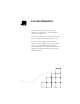
A-6 APPENDIX A: CABLING RJ-45 Connector Pin Assignments Figure A-1 shows the RJ-45 connector pin assignments.
B CONFIGURING SOFTWARE SETTINGS The Fast EtherLink 10/100BASE-T4 PCI adapter is automatically configured by the PCI’s computer’s BIOS with the following basic configuration parameters: ■ I/O Port Address ■ Interrupt Request Level (IRQ) This is done automatically when the computer with the installed Fast EtherLink PCI adapter is turned on for the first time after installation of the adapter. Other required parameters are preset on the adapter so that it will function without further action.
B-2 APPENDIX B: CONFIGURING SOFTWARE SETTINGS Table B-1 Option Settings Option Default Setting Available Settings Boot PROM Disabled Disabled, 8 K, 16 K, 32 K, 64 K Media Type 10BASE-T 100BASE-T4, 10BASE-T, Auto Select Network Driver Optimization* Normal Normal, Minimize CPU Utilization, Maximize Network Performance Full Duplex† Disabled Enabled (10 Mbps only), Disabled * This option specifies whether to optimize the network driver for a normal environment, a minimized CPU utilization envir
Changing Software Settings B-3 5 When the auto installation screen appears, as shown in Figure 3-1 press [Enter]. 6 When the main menu appears with a list of options, as shown in Figure 3-2, select Configuration/Diagnostic/ Troubleshooting. 7 When the Configuration and Diagnostic screen appears, select Configuration and Diagnostic Program. 8 Do one of the following: a If you have multiple adapters installed, as shown in Figure B-1, use the arrow keys to select the desired adapter and press [Enter].
B-4 APPENDIX B: CONFIGURING SOFTWARE SETTINGS In both cases, a screen similar to the one shown in Figure B-2 appears, showing the parameters for the selected adapter.
Changing Software Settings B-5 You must highlight OK and press [Enter] to save the settings. If you want to use the same settings on other adapters, you can save the configuration settings to a file. Select Save under File Options in the Adapter Configuration dialog box. For example, type: D:\CONFIG\3C595.SET This saves the settings to the default file 3C595.SET in the CONFIG directory in drive D. Refer to the on-line help (press [F1]) for more information.
C SPECIFICATIONS This appendix lists the specifications for the Fast EtherLink 10/100BASE-T4 PCI adapter. It also contains pin assignments for the adapter’s RJ-45 connector. Adapter Specifications Network Interface 10 Mbps Ethernet 10BASE-T Ethernet IEEE 802.3 industry standard for a 10 Mbps baseband CSMA/CD local area network 100 Mbps Ethernet 100BASE-T4 Ethernet IEEE 802.3u industry standard for a 100 Mbps baseband CSMA/CD local area network Physical Dimensions Length: 17.46 cm (6.
D TECHNICAL SUPPORT 3Com provides easy access to technical support information through the variety of services described in this appendix.
D-2 APPENDIX D: TECHNICAL SUPPORT Country Data Rate Telephone Number Japan up to 14400 bps (81) (3) 3345 7266 Singapore up to 14400 bps (65) 534 5693 Taiwan up to 14400 bps (886) (2) 377 5838 U.K. up to 28800 bps (44) (1442) 278278 U.S. up to 28800 bps (1) (408) 980 8204 Access by ISDN ISDN users can dial-in to 3Com BBS using a digital modem for fast access up to 56 Kbps.
Support from Your Network Supplier D-3 3ComFacts Automated Fax Service 3Com Corporation’s interactive fax service, 3ComFacts, provides data sheets, technical articles, diagrams, and troubleshooting instructions on 3Com products 24 hours a day, seven days a week. Call 3ComFacts using your touch-tone telephone. International access numbers are: Country Fax Number Hong Kong (852) 2537 5610 U.K. (44) (1442) 278279 U.S.
D-4 APPENDIX D: TECHNICAL SUPPORT ■ Details about recent configuration changes, if applicable If you are outside the U.S.
GLOSSARY 10BASE-T The IEEE 802.3 standard for a 10 Mbps baseband network on twisted-pair cable. 100BASE-FX The IEEE 802.3 standard for a 100 Mbps baseband network over two optical fibers. 100BASE-T The IEEE 802.3 standard for a 100 Mbps baseband network over twisted-pair cable. 100BASE-T4 The IEEE 802.3 standard for a 100 Mbps baseband network over four pair Category 3, 4, or 5 UTP wire. 100BASE-TX The IEEE 802.3 standard for a 100 Mbps baseband network over two pair Category 5 UTP or STP wire.
2 GLOSSARY Auto Select Media Type A utility that detects the type of network cable connected to the adapter and automatically selects that connection for packet transmission. This function is implemented by all NetWare ODI, Windows for Workgroups, NDIS 2.01, Windows NT, and Windows 95 drivers. Broadcast architecture The signaling scheme in which every node receives every broadcast from every other node at the same time.
GLOSSARY 3 EIA/TIA Electronics Industries Association/Telecommunications Industries Association. The organization that develops wiring standards for the telecommunications industry. The EIA/TIA 568 specification applies to all unshielded twisted-pair wiring schemes that work with Ethernet, Token Ring, ISDN and other networks. EISA Extended Industry Standard Architecture. The EISA 32-bit extended AT personal computer bus architecture is downward compatible with the 16-bit ISA architecture.
4 GLOSSARY MAC Media access control. The operational scheme that gives each network node orderly access to the network cable. CSMA/CD is a MAC protocol that determines how nodes on the network share access to the cable. NDIS Network Driver Interface Specification. Defines the LAN Manager network driver architecture and interfaces that let a DOS or OS/2 system support network adapters. This architecture provides a standardized way to write drivers for network adapters.
GLOSSARY 5 STP Shielded twisted-pair cable. Twisted-pair cabling with an overall shield to prevent the entry of outside interference, and individually shielded and twisted-pairs to prevent crosstalk. Transcend 3Com’s integrated network management solution based on groups of logically related devices and including a variety of network management tools.
INDEX Numerics 10/100BASE-T4 PCI adapter 1-3 100BASE-FX description A-5 100BASE-T media specifications A-4 standard A-4 100BASE-T4 description A-5 Fast Ethernet 1-1 100BASE-TX description A-4 Fast Ethernet 1-1 10BASE-T Ethernet, 10 Mbps 1-1 specifications A-3 three-repeater rule A-3 twisted-pair cable 1-2, A-3 3C595.SET B-5 3C595-T4 1-1 3C59X drivers 3-11 3C59X.LAN server driver 3-11 3C59XCFG 4-3 3Com Bulletin Board Service (3ComBBS) D-1 3Com sales offices D-4 3ComFacts D-3 3ComForum D-2 802.
2 INDEX D H DEC PATHWORKS 3-11 default option settings B-2 Desktop Management Interface (DMI) 1-3, 3-13 diagnostic program, starting 4-3 diagnostic tests 4-1 changing test setup 4-9 echo server 4-5 failed 4-7 for specific adapters 4-6 Group 1 4-2, 4-3, 4-4 Group 2 4-2 Group 3 (Echo Server) 4-2, 4-4 starting 4-3 DOS 3-6 accessing 3-2 DOS NDIS 3-12 DOS ODI client 1-3, 3-5, 3-7, 3-8 driver agents 3-13 drivers 1-1, 3-1 compatibility 3-2 NDIS 3-11, 3-12 NetWare ODI 3-5 summary of loading procedures 3-1 Windo
INDEX network connecting to 2-3 management 3-13 Network Driver Optimization option setting B-2 network supplier support D-3 NWCLIENT subdirectory 3-9 O on-line help 3-4 on-line technical services D-1 option settings changing B-2 OS/2 3-3 NDIS driver 3-12 3 S safety precautions 2-1 server driver, NetWare 3-11 shared slots 1-4 shielded twisted pair (STP) cable A-2 slots bus master 1-2 PCI 2-2, 4-7 shared 1-4 SmartAgent software 3-13 software option settings changing B-2 default B-2 saving B-5 specificatio
4 INDEX W Windows 3.
LIMITED WARRANTY HARDWARE: 3Com warrants its hardware products to be free from defects in workmanship and materials, under normal use and service, for the following lengths of time from the date of purchase from 3Com or its Authorized Reseller: Internetworking products Network adapters Ethernet stackable hubs and unmanaged Ethernet fixed port repeaters *Power supply and fans in these stackable hubs and unmanaged repeaters Other hardware products Spare parts and spares kits One year Lifetime Lifetime* (One
3COM SHALL NOT BE LIABLE UNDER THIS WARRANTY IF ITS TESTING AND EXAMINATION DISCLOSE THAT THE ALLEGED DEFECT IN THE PRODUCT DOES NOT EXIST OR WAS CAUSED BY CUSTOMER'S OR ANY THIRD PERSON'S MISUSE, NEGLECT, IMPROPER INSTALLATION OR TESTING, UNAUTHORIZED ATTEMPTS TO REPAIR, OR ANY OTHER CAUSE BEYOND THE RANGE OF THE INTENDED USE, OR BY ACCIDENT, FIRE, LIGHTNING, OR OTHER HAZARD.
FCC CLASS B CERTIFICATION 3Com Corporation Model No: 3C595-T4 FCC ID: DF63C595-T4 Made in U.S.A. This device complies with Part 15 of the FCC Rules. Operation is subject to the following two conditions: 1 this device may not cause harmful interference, and 2 this device must accept any interference received, including interference that may cause undesired operation.
CE NOTICE Marking by the symbol indicates compliance of this equipment to the EMC directive of the European Community. Such marking is indicative that this equipment meets or exceeds the following technical standards: ■ EN 55022—“Limits and Methods of Measurement of Radio Interference Characteristics of Information Technology Equipment.” ■ EN 50082-1—“Electromagnetic compatibility —Generic immunity standard Part 1: Residential, commercial, and light industry.