0-Port 100BASE-FX and 20-Port 10/100BASE-TX Fast Ethernet Layer 2 Switching Modules Quick Start Guide For the CoreBuilder® 9000 Enterprise Switch Module Descriptions This guide describes key installation information for two CoreBuilder® 9000 Fast Ethernet (FEN) Switching Modules: ■ The 10-port 100BASE-FX Fast Ethernet Layer 2 Switching Module (Model Number 3CB9LF10MC) has ten 100 Mbps Ethernet fiber-optic ports with SC connectors on its front panel and two 1-Gigabit ports on the back for connection to t
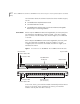
10-Port 100BASE-FX and 20-Port 10/100BASE-TX Fast Ethernet Layer 2 Switching Modules Quick Start Guide For information about the software features that these modules support, see the: Front Panel ■ CoreBuilder 9000 Implementation Guide ■ Command Reference Guide ■ CoreBuilder 9000 Release Notes for the Fast Ethernet and Gigabit Ethernet Layer 2 Switching Modules On the 10-port 100BASE-FX FEN Switching Module, the front panel ports are numbered 1 through 10, as shown in Figure 1.
10-Port 100BASE-FX and 20-Port 10/100BASE-TX Fast Ethernet Layer 2 Switching Modules Quick Start Guide Audience Description 3 This guide is intended for trained technical personnel only. Do not attempt to install, remove, or replace the 10/100BASE-TX or 100BASE-FX FEN Switching Modules if you have not had the proper training from 3Com. For training information in the United States and Canada, call 1-800-NET-3COM. For the numbers to call in other locations, visit the 3Com Web site: www.3Com.
10-Port 100BASE-FX and 20-Port 10/100BASE-TX Fast Ethernet Layer 2 Switching Modules Quick Start Guide ESD Safety Information Electrostatic discharge (ESD) can damage components of the module. ESD, which occurs when a module is improperly handled, can cause complete or intermittent failures. CAUTION: To prevent ESD-related damage: Handling Precautions ■ Always wear an ESD wrist strap (not provided) when you handle a module, ensuring that the strap makes good skin contact and is properly grounded.
10-Port 100BASE-FX and 20-Port 10/100BASE-TX Fast Ethernet Layer 2 Switching Modules Quick Start Guide Unpacking Instructions 5 Use the following procedure when you unpack a FEN Switching Module: 1 Verify that the module is the correct product by matching the 3C number that is listed on the shipping box label to the 3C number that you ordered (Model Number 3CB9LF10MC for the 10-port 100BASE-FX Fast Ethernet Layer 2 Switching Module or Model Number 3CB9LF20R for the 20-port 10/100BASE-TX Fast Ethernet Lay
10-Port 100BASE-FX and 20-Port 10/100BASE-TX Fast Ethernet Layer 2 Switching Modules Quick Start Guide Installation Prerequisites Before you install a module, make the following preparations: ■ Verify that the chassis is properly installed in a rack, on a table, or on a shelf, according to the instructions in either of these guides: ■ ■ 7-Slot Chassis Quick Installation Guide for the CoreBuilder 9000 Enterprise Switch Chassis Quick Installation Guide for the CoreBuilder 9000 Enterprise Switch 8-slot
10-Port 100BASE-FX and 20-Port 10/100BASE-TX Fast Ethernet Layer 2 Switching Modules Quick Start Guide ■ 7 In the 16-slot chassis: ■ ■ ■ Do not install the module in slot 8 or slot 9. These slots are reserved for GEN Switch Fabric Modules. Install the module in slot 1, 2, 3, 4, 5, 6, 7, 10, 11, or 12. 3Com recommends that you do not install the module in slot 13, 14, 15, or 16 because these slots have only one connection to the GEN Switch Fabric Module.
10-Port 100BASE-FX and 20-Port 10/100BASE-TX Fast Ethernet Layer 2 Switching Modules Quick Start Guide Table 1 Mapping the 24-port GEN SFM and the 10-port FEN Switching Module to the 7-slot Chassis Chassis Slot Number Number of SFM Backplane Ports Allocated to Slot 10-port Switching Module Backplane Port Numbers SFM Backplane Port Numbers Assigned to Chassis Slot SFM LED Numbers Assigned to Backplane Port Numbers 1 4; up to 2 can be accessed by this module 11 1 1 12 2 2 4; up to 2 can be ac
10-Port 100BASE-FX and 20-Port 10/100BASE-TX Fast Ethernet Layer 2 Switching Modules Quick Start Guide 9 Table 2 Mapping the 24-port GEN SFM and the 10-port FEN Switching Module to the 8-slot Chassis Chassis Slot Number Number of SFM Backplane Ports Allocated to Slot 10-port Switching Module Backplane Port Numbers SFM Backplane Port Numbers Assigned to Chassis Slot SFM LED Numbers Assigned to Backplane Port Numbers 1 4; up to 2 can be accessed by this module 11 1 1 12 2 2 4; up to 2 can be ac
10-Port 100BASE-FX and 20-Port 10/100BASE-TX Fast Ethernet Layer 2 Switching Modules Quick Start Guide Table 3 Mapping the 24-port GEN SFM and the 10-port FEN Switching Module to the 16-slot Chassis Chassis Slot Number Number of SFM Backplane Ports Allocated to Slot 10-port Switching Module Backplane Port Numbers SFM Backplane Port Numbers Assigned to Chassis Slot SFM LED Numbers Assigned to Backplane Port Numbers 1 2 11 1 1 12 2 2 11 3 3 12 4 4 11 5 5 12 6 6 11 7 7 12 8 8
10-Port 100BASE-FX and 20-Port 10/100BASE-TX Fast Ethernet Layer 2 Switching Modules Quick Start Guide Table 4 Mapping the 24-port GEN SFM and the 20-port FEN Switching Module to the 7-slot Chassis 20-port Switching Module SFM Backplane Port Backplane Port Numbers Assigned to Numbers Chassis Slot SFM LED Numbers Assigned to Backplane Port Numbers 4; up to 2 can be accessed by this module 21 1 1 22 2 2 4; up to 2 can be accessed by this module 21 5 3 22 6 4 4; up to 2 can be accessed by this
10-Port 100BASE-FX and 20-Port 10/100BASE-TX Fast Ethernet Layer 2 Switching Modules Quick Start Guide Table 5 Mapping the 24-port GEN SFM and the 20-port FEN Switching Module to the 8-slot Chassis Chassis Slot Number Number of SFM Backplane Ports Allocated to Slot 20-port Switching SFM Backplane Port Module Backplane Numbers Assigned to Port Numbers Chassis Slot SFM LED Numbers Assigned to Backplane Port Numbers 1 4; up to 2 can be accessed by this module 21 1 1 22 2 2 4; up to 2 can be ac
10-Port 100BASE-FX and 20-Port 10/100BASE-TX Fast Ethernet Layer 2 Switching Modules Quick Start Guide Table 6 Mapping the 24-port GEN SFM and the 20-port FEN Switching Module to the 16-slot Chassis Chassis Slot Number Number of SFM Backplane Ports Allocated to Slot 20-port Switching SFM Backplane Port Module Backplane Numbers Assigned to Port Numbers Chassis Slot SFM LED Numbers Assigned to Backplane Port Numbers 1 2 21 1 1 22 2 2 21 3 3 22 4 4 21 5 5 22 6 6 21 7 7 22 8 8 21
10-Port 100BASE-FX and 20-Port 10/100BASE-TX Fast Ethernet Layer 2 Switching Modules Quick Start Guide Table 7 Mapping the 9-port GEN SFM and the 10-port FEN Switching Module to the 7-slot Chassis Chassis Slot Number Number of SFM Backplane Ports Allocated to Slot 10-port Switching SFM Backplane Port Module Backplane Numbers Assigned to Port Numbers Chassis Slot SFM LED Numbers Assigned to Backplane Port Numbers 1 1 11 1 1 2 1 11 2 2 3 1 11 3 3 4 1 11 4 4 5 1 11 5 5 6 1 1
10-Port 100BASE-FX and 20-Port 10/100BASE-TX Fast Ethernet Layer 2 Switching Modules Quick Start Guide 15 Table 9 Mapping the 9-port GEN SFM and the 20-port FEN Switching Module to in the 7-slot Chassis Chassis Slot Number Number of SFM Backplane Ports Allocated to Slot 20-port Switching Module Backplane Port Numbers SFM Backplane Port Numbers Assigned to Chassis Slot SFM LED Numbers Assigned to Backplane Port Numbers 1 1 21 1 1 2 1 21 2 2 3 1 21 3 3 4 1 21 4 4 5 1 21 5 5 6
10-Port 100BASE-FX and 20-Port 10/100BASE-TX Fast Ethernet Layer 2 Switching Modules Quick Start Guide Installing the Module To install a FEN Switching Module: 1 Before you start the installation process, read and follow the instructions in “Safety Precautions,” “Handling Precautions,” and “Installation Prerequisites” earlier in this guide. 2 Select a chassis slot for your module, following the restrictions and recommendations in “Module Placement in the Chassis” earlier in this guide.
10-Port 100BASE-FX and 20-Port 10/100BASE-TX Fast Ethernet Layer 2 Switching Modules Quick Start Guide Figure 2 Installing a FEN Switching Module into a 7-Slot Chassis 20-port Fast Ethernet Switching Module ® CoreBuilder 9000 R 9 22 24 3 2 1 Spring-loaded screws 20 X 19 X 18 X 16 X 17 X 15 X 14 X 12 X 4 13 X 11 X 10 X 8X 9X 7X 6X 5X 4X 3X 2X 1X 5 3CB9LF20R 18 20 23 14 21 16 17 19 13 15 10 8 12 4 6 SE 2 9 7 ST AT 11 1 ST AT 7 1 2 3 4 5 6 M OD 6 14
10-Port 100BASE-FX and 20-Port 10/100BASE-TX Fast Ethernet Layer 2 Switching Modules Quick Start Guide Figure 3 Installing a FEN Switching Module into a 16-Slot Chassis Spring-loaded screw ® CoreBuilder 9000 R 1 2 3 4 5 6 7 MO D 7 8 MO D ST AT 14 1 2 3 4 5 6 1X 2X PR I 1 9 SE C 2 3 4 5 6 7 8 9 10 10 MO D ST AT PR I 1 ST AT SE C 2 3 4 5 6 7 8 9 10 11 12 11 12 13 14 13 14 15 16 15 16 17 18 17 18 19 20 19 20 21 22 21 22 23 24 23 24 3X
10-Port 100BASE-FX and 20-Port 10/100BASE-TX Fast Ethernet Layer 2 Switching Modules Quick Start Guide 19 7 To engage the module with the backplane, use both hands to perform the following steps: a Push firmly at the two ends of the front panel near the ejector handles until you feel the module connectors make firm contact with the backplane connectors. b Put your left thumb on the left or top ejector handle and your right thumb on the right or bottom ejector handle.
10-Port 100BASE-FX and 20-Port 10/100BASE-TX Fast Ethernet Layer 2 Switching Modules Quick Start Guide Verifying Module Operation The 10-port 100BASE-FX FEN Switching Module has 10 Port Status LEDs and the 20-port 10/100BASE-TX FEN Switching Module has 20 Port Status LEDs. Each module has one Module Status LED.
10-Port 100BASE-FX and 20-Port 10/100BASE-TX Fast Ethernet Layer 2 Switching Modules Quick Start Guide Managing the Module 21 You configure and manage a FEN Switching Module using several interfaces. The following sections describe two of the interfaces. Administration Console The Administration Console is the embedded menu-driven command line interface that you access from a terminal or through terminal emulation software. To manage the module from the Administration Console: 1 Log in to the EME.
10-Port 100BASE-FX and 20-Port 10/100BASE-TX Fast Ethernet Layer 2 Switching Modules Quick Start Guide Module Specifications The following tables list specifications for the 10-port 100BASE-FX and 20-port 10/100BASE-TX Fast Ethernet Layer 2 Switching Modules: Cabling Requirements Module Required Cable Type Maximum Segment Length 100BASE-FX (3CB9LF10MC) Multimode fiber 62.5/125 micron Half-duplex mode: 400 m (1312 ft Full-duplex mode: 2 km (1.
10-Port 100BASE-FX and 20-Port 10/100BASE-TX Fast Ethernet Layer 2 Switching Modules Quick Start Guide 23 Regulatory Compliance Safety Related CoreBuilder 9000 Documents Emissions ■ CSA 22.2 No.
10-Port 100BASE-FX and 20-Port 10/100BASE-TX Fast Ethernet Layer 2 Switching Modules Quick Start Guide You can view and print these and other current CoreBuilder 9000 documents from the following sources: ■ 3Com Web site http://support.3com.com/nav/switches.htm ■ CoreBuilder 9000 Documentation CD-ROM This CD-ROM is included in the chassis shipping box. You can also order the CD-ROM separately (Order Number 3CB9DB).
3Com Corporation LIMITED WARRANTY 10-Port 100BASE-FX Fast Ethernet Layer 2 Switching Module (Model Number 3CB9LF10MC) and 20-Port 10/100BASE-TX Fast Ethernet Layer 2 Switching Module (Model Number 3CB9LF20R) for the CoreBuilder® 9000 Enterprise Switch HARDWARE 3Com warrants to the end user (“Customer”) that this hardware product will be free from defects in workmanship and materials, under normal use and service, for one (1) year from the date of purchase from 3Com or its authorized reseller.
Advance Replacement is provided for ninety (90) days, after which time it may be available for a specified fee. 3Com will make commercially reasonable efforts to ship the replacement product not later than five (5) business days after receiving the request for advance replacement, but may be delayed due to product availability or export or import procedures. The shipment of advance replacement products is subject to local legal requirements and may not be available in all locations.
EMISSIONS COMPLIANCE STATEMENTS FOR CLASS A PRODUCTS Federal Communications Commission Notice This equipment has been tested and found to comply with the limits for a Class A digital device, pursuant to part 15 of the FCC rules. These limits are designed to provide reasonable protection against harmful interference when the equipment is operated in a commercial environment.
3Com Corporation 5400 Bayfront Plaza Santa Clara, California 95052-8145 Copyright © 1999, 3Com Corporation. All rights reserved. No part of this documentation may be reproduced in any form or by any means or used to make any derivative work (such as translation, transformation, or adaptation) without written permission from 3Com Corporation.