3Com Baseline Switch 2900 Family Getting Started Guide Manual Version: 5W100 www.3com.
Copyright © 2009, 3Com Corporation. All rights reserved. No part of this documentation may be reproduced in any form or by any means or used to make any derivative work (such as translation, transformation, or adaptation) without written permission from 3Com Corporation. 3Com Corporation reserves the right to revise this documentation and to make changes in content from time to time without obligation on the part of 3Com Corporation to provide notification of such revision or change.
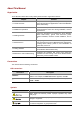
About This Manual Organization 3Com Baseline Switch 2900 Family Getting Started Guide is organized as follows: Chapter Contents 1 Product Overview Briefly introduces the appearance, system description, as well as the features and applications of the 3Com Baseline Switch 2900 Family. 2 Installation Preparations Describes the requirements on installation site, the safety recommendations before and during installation, and the required tools.
Convention Description Means a complementary description. Means techniques helpful for you to make configuration with ease.
Table of Contents 1 Product Overview ······································································································································1-1 Introduction ·············································································································································1-1 3Com Baseline Switch 2920-SFP Plus···································································································1-3 Front Panel ······························
Laser Safety ····································································································································2-2 Installation Tools ·····································································································································2-3 3 Installing a Switch ·····································································································································3-1 Installing the Switch into a 19-Inch Rack Using
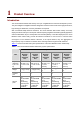
1 Product Overview Introduction The 3Com Baseline Switch 2900 Family are Layer 2 Gigabit Ethernet switches developed by 3Com. They are intelligent manageable switches designed for network environments where high performance, high-density port distribution, and easy installation are required.
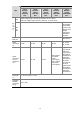
Description 3Com Baseline Switch 2920-SFP Plus Item AC 3Com Baseline Switch 2928-SFP Plus 3Com Baseline Switch 2952-SFP Plus 3Com Baseline Switch 2928-PWR Plus 3Com Baseline Switch 2928-HPWR Plus Rated voltage range: 100 VAC to 240 VAC, 50 Hz or 60 Hz Maximum voltage range: 90 VAC to 264 VAC, 47 Hz or 63 Hz — Use the external RPS unit provided by 3Com only, with the rated voltage ranging from –52 VDC to –55 VDC Supported RPS unit — RPS1000-A3 Power consumpti on 11.
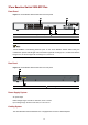
3Com Baseline Switch 2920-SFP Plus Front Panel Figure 1-1 3Com Baseline Switch 2920-SFP Plus front panel (1) 10/100/1000Base-T auto-sensing Ethernet port (3) Power LED (Power) (5) 1000Base-X SFP interface (2) Port status LED (4) Console port 10/100/1000Base-T autosensing Ethernet ports on the 3Com Baseline Switch 2900 Family are numbered in up-down and left-right order, with the first upper left one being Port 1, the first lower left one being Port 2, the second upper left one being Port 3, and so on.
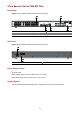
3Com Baseline Switch 2928-SFP Plus Front Panel Figure 1-3 3Com Baseline Switch 2928-SFP Plus front panel (1) 10/100/1000Base-T auto-sensing Ethernet port (3) Power LED (Power) (5) 1000Base-X SFP interface (2) Port status LED (4) Console port Rear Panel Figure 1-4 3Com Baseline Switch 2928-SFP Plus rear panel (1) AC receptacle (2) Grounding screw Power Supply System AC power input: Rated voltage range: 100 VAC to 240 VAC, 50 Hz or 60 Hz Input voltage range: 90 VAC to 264 VAC, 47 Hz or 63 Hz Cooling Sy
3Com Baseline Switch 2952-SFP Plus Front Panel Figure 1-5 3Com Baseline Switch 2952-SFP Plus front panel (1) 10/100/1000Base-T auto-sensing Ethernet port (3) Console port (5) 1000Base-X SFP interface (2) 10/100/1000Base-T auto-sensing Ethernet port status LED (4) Power LED (Power) (6) 1000Base-X SFP interface status LED Rear Panel Figure 1-6 3Com Baseline Switch 2952-SFP Plus rear panel (1) AC receptacle (2) Grounding screw Power Supply System AC power input: Rated voltage range: 100 VAC to 240 VAC, 5
3Com Baseline Switch 2928-PWR Plus Front Panel Figure 1-7 3Com Baseline Switch 2928-PWR Plus front panel (1) 10/100/1000Base-T auto-sensing Ethernet port (3) Port status LED (5) Port mode LED (7) 1000Base-X SFP interface (2) Port status LED mode switching button (4) Power LED (Power) (6) Console port Port Rear Panel Figure 1-8 3Com Baseline Switch 2928-PWR Plus rear panel (1) AC receptacle (2) Grounding screw Power Supply System AC power input: Rated voltage range: 100 VAC to 240 VAC, 50 Hz or 60 Hz I
3Com Baseline Switch 2928-HPWR Plus Front Panel Figure 1-9 3Com Baseline Switch 2928-HPWR Plus front panel (1) 10/100/1000Base-T auto-sensing Ethernet port (3) RPS status LED (RPS) (5) Power LED (Power) (7) Console port (2) Port status LED mode switching button (4) Port status LED (6) Port mode LED (8) Port 1000Base-X SFP interface Rear Panel Figure 1-10 3Com Baseline Switch 2928-HPWR Plus rear panel (1) Screw hole of the plug (3) Grounding screw (2) AC receptacle (4) DC power receptacle Power Supply
Only the RPS recommended by 3Com can be used for the 3Com Baseline Switch 2928-HPWR Plus. The –48 VDC power supply in the equipment room cannot be used directly. Otherwise, the device may be damaged. Cooling System The 3Com Baseline Switch 2928-HPWR Plus is equipped with six fans for heat dissipation. Ports Console Port Each 3Com Baseline Switch 2900 Family provides one console port on the front panel. Table 1-2 describes the console port specifications.
1000Base-X SFP Interface Each 3Com Baseline Switch 2900 Family provides four 1000Base-X SFP interfaces on its front panel. You can select the GE SFP transceivers described in Table 1-4. Table 1-4 Transceivers supported by the 3Com Baseline Switch 2900 Family 1000Base-X SFP interfaces Transceiver type Transceiver SFP-GE-SX-MM850-A Central wavelength Connector 850 nm Fiber 50/125 µm multimode optical fiber 550 m (0.34 miles) 62.5/125 µm multimode optical fiber 275 m (0.17 miles) 10 km (6.
LEDs Table 1-5 LEDs LED Device support Description Power LED All series See “Power LED” on page 1-10. RPS status LED 3Com Baseline Switch 2928-HPWR Plus See “RPS Status LED” on page 1-10. Port mode LED 3Com Baseline Switch 2928-PWR Plus and 3Com Baseline Switch 2928-HPWR Plus See “Port Mode LED” on page 1-11.
Port Mode LED The port mode LED on the 3Com Baseline Switch 2928-PWR Plus/3Com Baseline Switch 2928-HPWR Plus can display the working status of a port for you to obtain more device information. You can use the port mode switching button to change the status of the port mode LED. Table 1-8 3Com Baseline Switch 2928-PWR Plus/3Com Baseline Switch 2928-HPWR Plus port mode LED description LED Status Mode Description Solid green Indicates port rate. Blinking green (1 Hz) Indicates port PoE power supply.
Switch model 3Com Baseline Switch 2952-SFP Plus Port mode LED — Ethernet port status LED Meaning Solid green The port operates at a rate of 1000 Mbps Fast blinking green Data is transmitted or received at a rate of 1000 Mbps Solid yellow The port operates at a rate of 10/100 Mbps Fast blinking yellow Data is transmitted or received at a rate of 10/100 Mbps Off The port is not up or the POST has failed Green Solid green (rate mode) Yellow 3Com Baseline Switch 2928-PWR Plus 3Com Baseline Swit
1000Base-X SFP Interface Status LED For 3Com Baseline Switch 2928-PWR Plus and 3Com Baseline Switch 2928-HPWR Plus, the port mode switching button does not take effect for the 1000Base-X SFP interface LEDs. Table 1-10 1000Base-X SFP interface status LEDs description LED Solid green Meaning The port operates at a rate of 1000 Mbps The port is transmitting data at 1000 Mbps Blinking green The LED is fast blinking when data is being received on the port.
2 Installation Preparations Safety Precautions To avoid any device impairment and bodily injury caused by improper use, observe these rules: z Before cleaning the switch, plug out the power cord of the switch first. Do not clean the switch with wet cloth or liquid. z Do not place the switch near water or in a damp environment. Prevent water or moisture from entering the switch chassis. z Do not place the switch on an unstable case or desk. The switch might be damaged severely in case of a fall.
Especially when the indoor relative humidity is low, electrostatic adsorption is more likely to happen. This can not only shorten the service life of your device but also cause communications failures. The following table lists the dust concentration limit. Table 2-1 Dust concentration limit in the equipment room Substance Concentration limit (particles//m³) 4 Dust ≤ 3 x 10 (no visible dust on the tabletop over three days) Note: The dust diameter is greater than or equal to 5 μm.
When an SFP module on the 3Com Baseline Switch 2900 Family is operating, do not stare into the optical port because the laser light emitted from the optical fiber may hurt your eyes. Installation Tools z Flat-blade screwdriver z Phillips screwdriver z ESD-preventive wrist strap No installation tools are shipped with the 3Com Baseline Switch 2900 Family.
3 Installing a Switch On a mounting screw of the chassis of the 3Com series switches, there is a seal labeled. You need to keep it intact before asking the agent to maintain the switch. You need to get the permission of the local agent before you can open the chassis. Otherwise, you will be responsible for irreversible damages caused by your operations.
Figure 3-2 Two-holed mounting bracket (1) Screw hole used to fix the mounting bracket to the rack (with an M6 screw) (2) Screw hole used to fix the switch to the mounting bracket Figure 3-3 Four-holed mounting bracket (1) Screw hole used to fix the mounting bracket to the rack (with an M6 screw) (2) Screw hole used to fix the switch to the mounting bracket Attaching the Mounting Brackets to a Switch The installation of actual mounting brackets vary with devices.
The mounting brackets can be attached to a switch for center, front, or rear mounting. You can choose a proper position according to the actual requirements. Table 3-2 shows the position support for the 3Com Baseline Switch 2900 Family.
Figure 3-6 Install a four-holed mounting bracket on the chassis (front mounting) Figure 3-7 Install a four-holed mounting bracket on the chassis (center mounting) Figure 3-8 Install a four-holed mounting bracket on the chassis (rear mounting) Mounting the Switch to a Rack Step1 Put on an ESD-preventive wrist strap and make sure the rack is well grounded and is firm enough to hold the switch and cables. Step2 Attach the mounting brackets to the switch.
If support trays are provided on the rack, you can mount the switch to the rack with mounting brackets and trays. Put the switch on the support tray and slide the switch to an appropriate location. Then fix the mounting brackets. Figure 3-9 Mount the 3Com Baseline Switch 2928-PWR Plus to a rack Installation of other 3Com Baseline Switch 2900 Family into a rack is similar to that of the 3Com Baseline Switch 2928-PWR Plus.
Mounting the Switch on a Workbench In many cases, standard 19-inch cabinets are not available. Therefore, switches are often placed on clean workbenches. To place the switch on a workbench, follow these steps: Step1 Place the switch with bottom up carefully, and then clean the round holes on the chassis bottom with dry cloth. Step2 Attach the rubber feet to the four round holes on the chassis bottom. Step3 Place the switch with upside up on the workbench.
Figure 3-10 Connect the PGND cable to the grounding hole of switch (1) Rear panel of the switch (3) Grounding hole (5) PGND cable (2) Grounding sign (4) OT terminal (6) Grounding screw To attach the other end of the PGND cable to the grounding strip in the equipment room, follow these steps: Step1 Cut the PGND cable to a proper length according to the distance between the switch and the grounding strip. Step2 Peel 5 mm (0.20 in.
z The PGND cables supplied with the 3Com Baseline Switch 2900 Family do not provide OT terminals at the ends connecting the grounding strip. You need to prepare proper OT terminals by yourself. z The fire main and lightning rod of a building are not suitable for grounding the switch. The PGND cable of the switch should be connected to the grounding device for the equipment room.
Figure 3-13 Ground through an AC power PE wire (1) Three-wire AC power input cable (2) Switch rear panel Use the PGND cable provided with the switch to connect the grounding strip in the equipment room. Otherwise, the grounding effect may not be ensured, which easily causes damage to the switch. Connecting the Power Cord Connecting an AC Power Cord The 3Com Baseline Switch 2900 Family uses an external AC power system for its power supply.
Make sure that the PGND cable has been properly connected before powering on the switch. Connecting an RPS DC Power Cord The 3Com Baseline Switch 2928-HPWR Plus also supports RPS DC power input with the input voltage ranging from –52 V to –55 V. Follow these steps to install a DC power cord: Step1 Connect one end of the supplied PGND cable to the grounding screw on the rear panel of the chassis and the other end to the ground as near as possible.
z The selected power module matches that required by the switch. z The power cables are properly connected. z All the interface cables are cabled indoors. If there is any cable wired outdoors, verify that socket strip with lightning protection and lightning arresters for network ports have been properly connected.
4 Initial Power-On Setting Up the Configuration Environment Set up the configuration environment as follows: Connect a terminal (a PC in this example) to the console port on the switch with a console cable. Figure 4-1 Network diagram for configuration environment setup Connecting the Console Cable Console Cable A console cable is an 8-core shielded cable.
RJ-45 Signal Direction DB-9 3 TXD ← 3 4 CD → 1 5 GND — 5 6 RXD → 2 7 DSR → 6 8 CTS → 8 Connection Procedure When you want to use the terminal to configure the switch, follow these steps to connect a terminal device to the switch using the console cable: 1) Plug the DB-9 female connector of the console cable to the serial port of the console terminal or PC. 2) Connect the RJ-45 connector of the console cable to the console port of the switch.
z Data bits: 8 z Parity: None z Stop bits: 1 z Flow control: None z Emulation: VT100 The specific procedure is as follows: Step1 Select Start > Programs > Accessories > Communications > HyperTerminal to enter the HyperTerminal window. The Connection Description dialog box appears, as shown below. Figure 4-3 Connection description of the HyperTerminal Step2 Type the name of the new connection in the Name text box and click OK. The following dialog box appears.
Step3 Click OK after selecting a serial port. The following dialog box appears. Set Bits per second to 38400, Data bits to 8, Parity to None, Stop bits to 1, and Flow control to None. Figure 4-5 Set the serial port parameters Step4 Click OK after setting the serial port parameters and the system enters the HyperTerminal window shown below.
Step5 Click Properties in the HyperTerminal window to enter the Switch Properties dialog box. Click the Settings tab, set the emulation to VT100, and then click OK. Figure 4-7 Set terminal emulation in Switch Properties dialog box Booting the Switch Checking Before Power-On Before powering on the switch, verify that: z The power cable is properly connected. z The power supply voltage meets the requirement of the switch.
CPU Clock Speed : 333MHz Memory Type : DDR2 SDRAM Memory Size : 128MB Flash Size : 128MB CPLD Version : 001 PCB Version : Ver.A Mac Address : 000ef2002900 Press Ctrl-B to enter Extended Boot menu...1 The last line asks whether you want to enter the Boot ROM menu. The system waits one second for your response. z The system has two startup modes: normal startup and fast startup.
Item z Description 6. Enter BootRom upgrade menu Enter the Boot ROM update menu 7. Skip current system configuration Skip the current configuration file (this configuration is valid once) 8. Set BootRom password recovery Restore the Boot ROM password 9. Set switch startup mode Set the startup mode of the switch 0.
Are you sure you want to change it to full startup mode? Yes or No (Y/N): Enter Y. The system displays the following information: Setting...Done! BOOT MENU 1. Download application file to flash 2. Select application file to boot 3. Display all files in flash 4. Delete file from flash 5. Modify BootRom password 6. Enter BootRom upgrade menu 7. Skip current system configuration 8. Set BootRom password recovery 9. Set switch startup mode 0. Reboot Enter your choice(0-9): Enter 0.
CPLD selftest................................OK! Switch chip selftest.........................OK! PHY selftest.................................OK! Please check leds......................FINISHED! User interface aux0 is available. Press ENTER to get started. Press Enter and enter the correct username (admin by default) and password (no password by default). The following prompt is displayed: <3Com Baseline Switch > You can configure the switch now.
5 Loading Software Introduction The 3Com Baseline Switch 2900 Family does not provide independent Boot ROM program but integrates it with the application program in host software package with the extension name of .bin. z Loading application files: Download the host software package to the flash memory on the switch and set the attribute (main, backup, or none) of the application files.
Introduction to the Boot ROM Menu Starting...... ************************************************************************ * * * 3COM 2928-SFP Plus BOOTROM, Version 102 * * * ************************************************************************ Creation Date : Jan 8 2009 CPU Type : ARM926 CPU L1 Cache : 32KB CPU Clock Speed : 333MHz Memory Type : DDR2 SDRAM Memory Size : 128MB Flash Size : 128MB CPLD Version : 001 PCB Version : Ver.
5. Modify BootRom password 6. Enter BootRom upgrade menu 7. Skip current system configuration 8. Set BootRom password recovery 9. Set switch startup mode 0. Reboot Enter your choice(0-9): The items in the Boot ROM menu are described in Table 4-2 z Currently, Boot ROM files are not provided separately by the 3Com Baseline Switch 2900 Family; instead, they are stored together with application files in the files with the name extension of .bin.
Task Remarks Required Set the download rate of the console port on the switch Log in to the switch through the HyperTerminal and then set the download rate of the console port on the switch.
After the system displays “Enter your choice(0-3):”, enter 1 to enter the protocol parameter setting menu. All the Boot ROM files to be loaded are complete Boot ROM files. 1. Set TFTP protocol parameter 2. Set FTP protocol parameter 3. Set XMODEM protocol parameter 0. Return to boot menu Enter your choice(0-3): The items in the protocol parameter setting menu are described in Table 5-3. Table 5-3 Description of the protocol parameter setting menu Item Description 1.
Now that the console communication baud rate of the switch has been changed to 115200 bps while that of the terminal is still 38400 bps, the two sides cannot communicate with each other. According to the prompt, you need to change the baud rate of the terminal to 115200 bps. z Typically, the size of a .bin file is over 9 MB. Even at a baud rate of 115200 bps, the update takes tens of minutes.
Figure 5-2 Properties dialog box Figure 5-3 Modify the baud rate Step3 Select Call > Call to reestablish the connection.
Figure 5-4 Reestablish the connection The new settings can take effect only after you reestablish the connection. 6) Establish a connection between the terminal and the switch using the changed rate Press Enter to reestablish the connection between the terminal and the switch and download the application file at 115200 bps. The following information is displayed: Now please start transfer file with XMODEM protocol If you want to exit, Press Loading ...
Figure 5-6 File transmission dialog box Step2 Click Send. The following dialog box appears: Figure 5-7 Send the application file using XMODEM 8) Updating the Boot ROM file on the switch After the Boot ROM file is downloaded, the terminal displays the following information: Loading ...CCCC Done! Will you Update Basic BootRom? (Y/N):Y The system asks you whether you want to update the basic Boot ROM section. Click Y and then the system displays the following information after the update is completed.
Set the baud rate to 38400 bps (refer to “Change the rate of the serial port on the terminal” on page 5-6 for detailed operation). If you select 38400 bps as the download rate, skip this step, that is, you do not need to modify the baud rate of the HyperTerminal. 10) Restarting the switch to make the updated Boot ROM file effective Press any key to return to the Boot ROM update menu. 1. Update full BootRom 2. Update extended BootRom 3. Update basic BootRom 0.
Loading Files Using TFTP Through Ethernet Port Introductin to TFTP Trivial File Transfer Protocol (TFTP) is a TCP/IP protocol used for file transfer between client and server. It provides a simple and low-overhead file transfer service. TFTP provides unreliable data transfer over UDP.
The PC and the TFTP server can be the same device. 2) Run the TFTP Server program on the sever Run TFTP Server on the server connected with the switch’s Ethernet port, and specify the path of the application file to be downloaded. 3) Run the terminal emulation program on the PC connected with the switch’s console port. Start the switch and enter the Boot ROM menu. Then enter the protocol parameter setting menu.
z Enter the file name and IP addresses based on the actual condition. z If the switch and the server are on the same network segment, you can specify any unused IP address of the network for the switch without specifying the gateway’s IP address; if they are not on the same segment, you need to specify the gateway’s IP address so that the switch can communicate with the server. 6) Update the Boot ROM file on the switch Enter the corresponding parameters based on the actual condition.
The procedure of loading an application file is similar to that of loading a Boot ROM file. The difference lies in that the system displays the prompt of loading the application file rather than the Boot ROM file. After loading the application file, the switch displays that you should configure the application attribute, that is, main, backup, or none. Type a specific attribute to complete loading the application file. Writing flash.................................................................. .........
1) Set up the configuration environment Connect an Ethernet port of the switch to the server (whose IP address is available) that provides the file (usually the .bin file) to be downloaded, and connect the console port of the switch to a PC, as shown in Figure 5-9.
Table 5-5 Description of the FTP parameters Item Load File Name Description : Name of the file to be downloaded Server IP Address : IP address of the PC Local IP Address : IP address of the switch Gateway IP Address : IP address of the gateway FTP User Name Username for logging in to the FTP server, which should be consistent with that configured on the FTP server. FTP User Password Password for logging in to the FTP server, which should be consistent with that configured on the FTP server.
Loading an application file To load an application file of the switch, enter 1 in the Boot ROM menu. The system displays the following information: 1. Set TFTP protocol parameter 2. Set FTP protocol parameter 3. Set XMODEM protocol parameter 0. Return to boot menu Enter your choice(0-3):3 You can enter 2 to load the application file. The procedure of loading an application file is similar to that of loading a Boot ROM file.
6 Maintenance and Troubleshooting File Loading Failure If file loading fails, the system runs steadily using the original system files. In this case, check whether the physical ports are properly connected. z If not, reconnect them correctly and restart the loading procedure. z If so, view the loading procedure information displayed on the HyperTerminal to check for input errors. If there is any input error, restart the loading procedure with correct input.
Power Supply Failure The 3Com Baseline Switch 2928-HPWR Plus adopts AC power input, RPS power input, or both RPS and AC power inputs. Other 3Com Baseline Switch 2900 Family adopt AC power input only. You can determine whether the power system of a switch functions normally by viewing the power LED or RPS power LED on the front panel. With AC power input When AC power input is used for power supply of a switch, you can check the power LED. The power LED stays on when power system is normal.
z The RPS power input is normal. If the cause cannot be located in the preceding steps and the problem persists, contact your local sales agent or service engineer. Configuration Terminal Failure After the switch is powered on and the system is normal, the booting information will be displayed on the configuration terminal. If the configuration system has any faults, there will not be any screen display at the configuration terminal or the displayed characters will be totally illegible.