User Guide 3Com Outdoor 11a Building to Building Bridge and 11bg Access Point 3CRWEASYA73 / WL-575 www.3Com.com Part Number 10015232 Rev.
3Com Corporation 350 Campus Drive Marlborough, MA 01752-3064 Copyright © 2006 3Com Corporation. All rights reserved. No part of this documentation may be reproduced in any form or by any means or used to make any derivative work (such as translation, transformation, or adaptation) without written permission from 3Com Corporation.
Contents 1 Introduction Product Features 1-1 Radio Characteristics 1-2 APPROVED CHANNELS 1-2 Package Checklist 1-3 Hardware Description 1-4 Integrated High-Gain Antenna 1-4 External Antenna Options 1-4 Ethernet Port 1-5 Power Injector Module 1-5 Grounding Point 1-6 Water Tight Test Point 1-6 Wall- and Pole-Mounting Bracket Kit 1-7 System Configuration 1-7 Operating Modes 1-7 Point-to-Point Configuration 1-8 Point-to-Multipoint Configuration 1-8 2 Bridge Link Planning Data Rates 2-2 Radio Path Planning 2-
Using the Pole-Mounting Bracket Using the Wall-Mounting Bracket Connect External Antennas 3-6 Connect Cables to the Unit 3-7 Connect the Power Injector 3-7 Check the LED Indicators 3-9 Align Antennas 3-10 4 3-2 3-4 Initial Configuration Networks with a DHCP Server 4-1 Networks without a DHCP Server 4-1 Using the 3Com Installation CD 4-2 Launch the 3COM Wireless Infrastructure Device Manager (Widman) utility 4-2 Launching the 3com Wireless Interface Device Manager 4-2 First Time Only 4-4 Using the Setup W
RSSI 5-35 Radio Interface 5-37 802.11a Interface 5-38 Configuring Radio Settings 5-38 Configuring Common Radio Settings 5-39 802.
Straight-Through Wiring B-3 Crossover Wiring B-4 8-Pin DIN Connector Pinout B-5 8-Pin DIN to RJ-45 Cable Wiring B-6 Glossary Index vi
TERMINOLOGY Access Point—An internet working device that seamlessly connects wired and wireless networks. Ad Hoc—An ad hoc wireless LAN is a group of computers, each with wireless adapters, connected as an independent wireless LAN. Backbone—The core infrastructure of a network. The portion of the network that transports information from one central location to another central location where it is unloaded onto a local system.
RTS Threshold—Transmitters contending for the medium may not be aware of each other (they are “hidden nodes”). The RTS/CTS mechanism can solve this problem. If the packet size is smaller than the preset RTS Threshold size, the RTS/CTS mechanism will not be enabled. VAP—Virtual Access Point. An access point radio capable of operating as four separate access points. VLAN—Virtual Local Area Network.
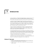
1 INTRODUCTION The 3Com Outdoor 11a Building to Building Bridge and 11bg Access Point system provides point-to-point or point-to-multipoint bridge links between remote Ethernet LANs, and wireless access point services for clients in the local LAN area. It includes an integrated high-gain antenna for the 802.11a radio and can operate as a “Slave” or “Master” bridge in point-to-multipoint configurations, or provide a high-speed point-to-point wireless link between two sites that can be up to 15.4 km (9.
Provides access point services for the 5 GHz and 2.4 GHz radios using various external antenna options Maximum data rate up to 108 Mbps on the 802.11a (5 GHz) radio Outdoor weatherproof design IEEE 802.11a and 802.
PACKAGE CHECKLIST The 3Com Outdoor 11a Building to Building Bridge and 11bg Access Point package includes: One 3Com Outdoor 11a Building to Building Bridge and 11bg Access Point Mounting bracket and hardware One Weatherproof Category 5 network cable One Weatherproof Console to RS232 cable PoE power injector/ Ethernet connector and AC power cord One grounding screw, not attached One Quick Start Guide One CD-ROM containing the Setup Wizard software and User’s Manual One Warranty Flyer Opt
HARDWARE DESCRIPTION Bottom Water Tight Test Point (DO NOT REMOVE) Console Port Cap Attachment Console Port with Protective Cap Ethernet/PoE Connector Grounding Point Integrated Antenna Top View N-Type External Antenna Connector (2.4 GHz) N-Type External Antenna Connector (5 GHz) INTEGRATED HIGH-GAIN ANTENNA The WL-575 bridge includes an integrated high-gain (17 dBi) flat-panel antenna for 5 GHz operation.
Item Antenna Type 2.4 GHz 5.0 GHz Gain (dBi) Horizontal HPBW* (Degrees) Vertical HPBW* (Degrees) 3CWE591 3Com 6/8 dBi Dual-Band Omni 6 8 360 5GHz: 20 2.4GHz: 30 3CWE596 3Com 18/20 dBi Dual-Band Panel 18 20 18 19 3CWE598 3Com 8/10 dBi Dual-Band Panel 8 10 60 60 * Half-power beam width External antennas connect to the N-type RF connectors on the wireless bridge using the optional RF coaxial cables.
network interconnection devices such as a switch or router that provide MDI-X ports. However, when connecting the access point to a workstation or other device that does not have MDI-X ports, you must use crossover twisted-pair cable. LED Indicator Input AC Power Socket (Hidden) Output Ethernet from Local Network Ethernet and Power to Wireless Bridge The wireless bridge does not have a power switch.
WALL- AND POLE-MOUNTING BRACKET KIT The wireless bridge includes a bracket kit that can be used to mount the bridge to a wall, pole, radio mast, or part of a tower structure. SYSTEM CONFIGURATION At each location where a unit is installed, it must be connected to the local network using the power injector module. The following figure illustrates the system component connections.
The wireless bridge modes connect two or more wired networks, for example networks in different buildings with no wired connections. You will need a 3Com Outdoor 11a Building to Building Bridge and 11bg Access Point unit on both sides of the connection. The wireless bridge can connect up to six remote networks. When using bridge mode on a radio band, only wireless bridge units can associate to each other. Wireless clients can only associate with the unit using a radio band set to access point mode.
The following figure shows a point-to-multipoint “in-line” configuration with one bridge set to “Master” and using a directional panel antenna.
1-10
2 BRIDGE LINK PLANNING The 3Com Outdoor 11a Building to Building Bridge and 11bg Access Point supports fixed point-to-point or point-to-multipoint wireless links. A single link between two points can be used to connect a remote site to larger core network. Multiple bridge links can provide a way to connect widespread Ethernet LANs. For each link in a wireless bridge network to be reliable and provide optimum performance, some careful site planning is required.
DATA RATES Using the 5.0 GHz integrated antenna, two WL-575 bridges can operate over a range of up to 15.4 km (9.6 miles) or provide a high-speed connection of 54 Mbps (108 Mbps in turbo mode). However, the maximum data rate for a link decreases as the operating range increases. A 15.4 km link can only operate up to 6 Mbps, whereas a 108 Mbps connection is limited to a range of 1.3 km.
RADIO PATH PLANNING Although the wireless bridge uses IEEE 802.11a radio technology, which is capable of reducing the effect of multipath signals due to obstructions, the wireless bridge link requires a “radio line-of-sight” between the two antennas for optimum performance. The concept of radio line-of-sight involves the area along a radio link path through which the bulk of the radio signal power travels. This area is known as the first Fresnel Zone of the radio link.
• Be sure there is enough clearance from buildings and that no building construction may eventually block the path. • Check the topology of the land between the antennas using topographical maps, aerial photos, or even satellite image data (software packages are available that may include this information for your area) • Avoid a path that may incur temporary blockage due to the movement of cars, trains, or aircraft.
Note that to avoid any obstruction along the path, the height of the object must be added to the minimum clearance required for a clear radio line-of-sight. Consider the following simple example, illustrated in the figure below. Radio Line of Sight Visual Line of Sight 3 miles (4.8 km) 2.4 m A 5.4 m B 1.4 m 9m 20 m 17 m 12 m A wireless bridge link is deployed to connect building A to a building B, which is located three miles (4.8 km) away.
ANTENNA POSITION AND ORIENTATION Once the required antenna height has been determined, other factors affecting the precise position of the wireless bridge must be considered: • Be sure there are no other radio antennas within 2 m (6 ft) of the wireless bridge • Place the wireless bridge away from power and telephone lines • Avoid placing the wireless bridge too close to any metallic reflective surfaces, such as roof-installed air-conditioning equipment, tinted windows, wire fences, or water pipes • The wire
RADIO INTERFERENCE The avoidance of radio interference is an important part of wireless link planning. Interference is caused by other radio transmissions using the same or an adjacent channel frequency. You should first scan your proposed site using a spectrum analyzer to determine if there are any strong radio signals using the 802.11a channel frequencies. Always use a channel frequency that is furthest away from another signal.
• Snow and Ice — Falling snow, like rain, has no significant effect on the radio signal. However, a build up of snow or ice on antennas may cause the link to fail. In this case, the snow or ice has to be cleared from the antennas to restore operation of the link. ETHERNET CABLING When a suitable antenna location has been determined, you must plan a cable route form the wireless bridge outdoors to the power injector module indoors.
3 HARDWARE INSTALLATION Before mounting antennas to set up your wireless bridge links, be sure you have selected appropriate locations for each antenna. Follow the guidance and information in Chapter 2, “Wireless Link Planning.” Also, before mounting units in their intended locations, you should first perform initial configuration and test the basic operation of the wireless bridge links in a controlled environment over a very short range. (See the section “Testing Basic Link Operation” in this chapter.
TESTING BASIC LINK OPERATION Set up the units over a very short range (15 to 25 feet), either outdoors or indoors. Connect the units as indicated in this chapter and be sure to perform all the basic configuration tasks outlined in Chapter 4, “Initial Configuration.” When you are satisfied that the links are operating correctly, proceed to mount the units in their intended locations.
2 Fit the edges of the V-shaped part into the slots in the rectangular plate, and tighten the nuts. Fit the edges of the V-shaped part into the slots 3 Attach the adjustable rectangular plate to the bridge with supplied screws.
4 Attach the bridge with bracket to the plate already fixed to the pole. Attach the bridge to the plate on the pole 5 Use the included nuts to secure the wireless bridge to the pole bracket. Note that the wireless bridge tilt angle may need to be adjusted during the antenna alignment process. Be sure to take account of the antenna polarization direction; all antennas in a link must be mounted with the same polarization.
1 Always attach the bracket to a wall with flat side flush against the wall (see following figure). 2 Position the bracket in the intended location and mark the position of the four mounting screw holes. 3 Drill four holes in the wall that match the screws and wall plugs included in the bracket kit, then secure the bracket to the wall. 4 Use the included nuts to tightly secure the wireless bridge to the bracket.
CONNECT EXTERNAL ANTENNAS The bridge’s primary antenna is it’s built-in internal antenna. For some applications when deploying an WL-575 unit for a bridge link or access point operation, you may need to mount external antennas and connect them to the bridge. Typically, a bridge link requires a 5.0 GHz antenna, and access point operation a 2.4 GHz antenna. WL-575 units acting as managed APs also require an external antenna for 2.4 GHz operation.
CONNECT CABLES TO THE UNIT ! ! WARNING: Do not connect or disconnect cables or otherwise work with the bridge during periods of lightning activity. 1 Attach the Ethernet cable to the Ethernet port on the wireless bridge. 2 For extra protection against rain or moisture, apply weatherproofing tape (not included) around the Ethernet connector. 3 Be sure to ground the unit with an appropriate grounding wire (not included) by attaching it to the grounding screw on the unit.
NOTE: The wireless bridge’s Ethernet port does not support Power over Ethernet (PoE) based on the IEEE 802.3af standard. Do not try to power the unit by connecting it directly to a network switch that provides IEEE 802.3af PoE. Always connect the unit to the included power injector module. 1 Connect the Ethernet cable from the wireless bridge to the RJ-45 port labeled “Output” on the power injector.
CHECK THE LED INDICATORS The bridge’s 11a and 11b/g LEDs operate in two display modes, which are configurable through the software. The default AP mode indicates data traffic rates. The RSSI mode indicates the received signal power and is for use when aligning antennas in a bridge link. When the bridge is connected to power, the LEDs indicate as follows: 11b/g 11a LED Color Indicates Power Green The bridge is powered up and operating normally.
LED Color Indicates 11g (Three LEDs) Amber and Flashing The 802.11g 2.4 GHz radio is enabled. RSSI Mode: One fully lit LED indicates a low RSSI output level, two LEDs.a medium level, and three LEDs the maximum level. A flashing LED indicates an intermediate RSSI output level AP Mode: One fully lit LED indicates a low traffic rate, two LEDs.a medium rate, and three LEDs the maximum rate. A flashing LED indicates an intermediate traffic rate level Off No link is present or the 802.
When you move the antenna during alignment, the radio signal from the remote antenna can be seen to have a strong central main lobe and smaller side lobes. The object of the alignment process is to set the antenna so that it is receiving the strongest signal from the central main lobe.
1 Pan the antenna horizontally back and forth while checking the LEDs. If using the pole-mounting bracket with the unit, you must rotate the mounting bracket around the pole. Other external antenna brackets may require a different horizontal adjustment. 2 Find the point where the signal is strongest (all LEDs on) and secure the horizontal adjustment in that position.
4 INITIAL CONFIGURATION The 3Com Outdoor 11a Building to Building Bridge and 11bg Access Point offers a variety of management options, including a web-based interface. The initial configuration steps can be made through the web browser interface. The access point requests an IP address via DHCP by default. If no response is received from the DHCP server, then the access point uses the default address 169.254.2.1.
CHAPTER 4: INITIAL CONFIGURATION 1 Connect a computer directly to the Access Point using the supplied standard Category 5 UTP Ethernet cable. 2 Enter the Access Point’s default IP address (169.254.2.1) into the computer’s web browser. If the Configuration Management System starts, the Access Point is using the factory assigned IP address.
Figure 1 Wireless Interface Device Manager Click on the Properties button to see the following screen Figure 2 Wireless Interface Device Manager - Properties 4-3
CHAPTER 4: INITIAL CONFIGURATION Directly connect to the device through its Ethernet port or console port. Follow the instructions below to login into the AP Configuration screen: 1 Load a web browser and enter . 2 The Logon screen appears. To log on to the Web interface: 1 Username, type admin (case sensitive). 2 Password, type password 3 Click Log On. FIRST TIME ONLY When you log in for the first time, you may be asked to select your country.
Using the Setup Wizard NOTE: If you changed the default IP address via the command line interface above, use that address instead of the one shown here. Logging In – Enter the username “admin,” and password “password,” then click LOGIN. For information on configuring a user name and password, see page 23.
CHAPTER 4: INITIAL CONFIGURATION The home page displays the Main Menu. Figure 4 Home Page Launching the Setup Wizard – To perform initial configuration, click Setup Wizard on the home page, select the VAP you wish to configure, then click on the [Next] button to start the process. Figure 5 Setup Wizard - Start 1 Service Set ID – Enter the service set identifier in the SSID box which all wireless clients must use to associate with the access point.
Using the Setup Wizard Figure 6 Setup Wizard - Step 1 2 Radio Channel – You must enable radio communications for 802.11a and 802.11b/g, and set the operating radio channel. NOTE: Available channel settings are limited by local regulations, which determine the channels that are available. This User Guide shows channels and settings that apply to North America (United States and Canada), with 13 channels available for the 802.11a interface and 11 channels for the 802.11g interface.
CHAPTER 4: INITIAL CONFIGURATION 802.11a Turbo Mode – If you select Enable, the access point will operate in turbo mode with a data rate of up to 108 Mbps. Normal mode support 13 channels, Turbo mode supports only 5 channels. (Default: Disabled) 802.11a Radio Channel – Set the operating radio channel number. (Default: 60ch, 5.300 GHz) Auto Channel Select – Select Enable for automatic radio channel detection. (Default: Enabled) 802.
Using the Setup Wizard NOTE: If there is no DHCP server on your network, then the access point will automatically start up with its default IP address, 169.254.2.1. 4 Security – Set the Authentication Type to “Open” to allow open access without authentication, or “Shared” to require authentication based on a shared key. Enable encryption to encrypt data transmissions. To configure other security features use the Advanced Setup menu as described in Chapter 4.
CHAPTER 4: INITIAL CONFIGURATION NOTE: All wireless devices must be configured with the same Key ID values to communicate with the access point. 5 Click Finish. 6 Click the OK button to complete the wizard.
5 SYSTEM CONFIGURATION Before continuing with advanced configuration, first complete the initial configuration steps described in Chapter 4 to set up an IP address for the access point. The access point can be managed by any computer using a web browser (such as Internet Explorer 5.0 or above). Enter the configured IP address of the access point, or use the default address: http://169.254.2.1. To log into the access point, enter the default user name “admin” and the password “password,” then press “LOGIN.
CHAPTER 5: SYSTEM CONFIGURATION Figure 11 Advanced Setup The information in this chapter is organized to reflect the structure of the web screens for easy reference. However, it is recommended that you configure a user name and password as the first step under Administration to control management access to this device (page 5-23). ADVANCED SETUP The Advanced Setup pages include the following options.
Advanced Setup Menu Description Page SNMP Configures SNMP settings 5-19 Administration Configures user name and password for management access; upgrades software from local file, FTP or TFTP server; resets configuration settings to factory defaults; and resets the access point 5-23 WDS/STP Settings Configures WDS bridging and Spanning Tree Protocol features 5-28 Syslog Set-up Controls logging of error messages; sets the system clock via SNTP server or manual configuration 5-33 RSSI Configur
CHAPTER 5: SYSTEM CONFIGURATION SYSTEM IDENTIFICATION The system name for the access point can be left at its default setting. However, modifying this parameter can help you to more easily distinguish different devices in your network. Figure 12 System Identification System Name – An alias for the access point, enabling the device to be uniquely identified on the network.
TCP / IP Settings TCP / IP SETTINGS Configuring the access point with an IP address expands your ability to manage the access point. A number of access point features depend on IP addressing to operate. NOTE: You can use the web browser interface to access IP addressing only if the access point already has an IP address that is reachable through your network. By default, the access point will be automatically configured with IP settings from a Dynamic Host Configuration Protocol (DHCP) server.
CHAPTER 5: SYSTEM CONFIGURATION DHCP Client (Enable) – Select this option to obtain the IP settings for the access point from a DHCP (Dynamic Host Configuration Protocol) server. The IP address, subnet mask, default gateway, and Domain Name Server (DNS) address are dynamically assigned to the access point by the network DHCP server. (Default: Enabled) DHCP Client (Disable) – Select this option to manually configure a static address for the access point.
TCP / IP Settings Figure 14 Smart Monitor By enabling Smart Monitor (known as Link Integrity in the CLI) and setting a target IP address, the AP will periodically (set by the ping interval) check to see if the target address responds to pings. If it fails to respond to a ping after the configured number of retries, it will disable both radios so that no clients can connect to the AP.
CHAPTER 5: SYSTEM CONFIGURATION RADIUS Remote Authentication Dial-in User Service (RADIUS) is an authentication protocol that uses software running on a central server to control access to RADIUS-aware devices on the network. An authentication server contains a database of user credentials for each user that requires access to the network. A primary RADIUS server must be specified for the access point to implement IEEE 802.1X network access control and Wi-Fi Protected Access (WPA) wireless security.
RADIUS Figure 15 RADIUS Authentication Primary Radius Server Setup – Configure the following settings to use RADIUS authentication on the access point. IP Address: Specifies the IP address or host name of the RADIUS server. Port: The UDP port number used by the RADIUS server for authentication messages. (Range: 1024-65535; Default: 1812) Key: A shared text string used to encrypt messages between the access point and the RADIUS server.
CHAPTER 5: SYSTEM CONFIGURATION Secondary Radius Server Setup – Configure a secondary RADIUS server to provide a backup in case the primary server fails. The access point uses the secondary server if the primary server fails or becomes inaccessible. Once the access point switches over to the secondary server, it periodically attempts to establish communication again with primary server. If communication with the primary server is re-established, the secondary server reverts to a backup role.
Authentication The access point can also operate in a 802.1X supplicant mode. This enables the access point itself to be authenticated with a RADIUS server using a configured MD5 user name and password. This prevents rogue access points from gaining access to the network. Take note of the following points before configuring MAC address or 802.1X authentication: Use MAC address authentication for a small network with a limited number of users.
CHAPTER 5: SYSTEM CONFIGURATION Figure 16 Authentication MAC Authentication – You can configure a list of the MAC addresses for wireless clients that are authorized to access the network. This provides a basic level of authentication for wireless clients attempting to gain access to the network. A database of authorized MAC addresses can be stored locally on the access point or remotely on a central RADIUS server.
Authentication Authentication section of this web page to set up the local database, and configure all access points in the wireless network service area with the same MAC address database. Radius MAC: The MAC address of the associating station is sent to a configured RADIUS server for authentication. When using a RADIUS authentication server for MAC address authentication, the server must first be configured in the Radius window (see “RADIUS” on page 8).
CHAPTER 5: SYSTEM CONFIGURATION Session Key Refresh Rate: The interval at which the access point refreshes unicast session keys for associated clients. (Range: 0-1440 minutes; Default: 0 means disabled) 802.1X Reauthentication Refresh Rate: The time period after which a connected client must be re-authenticated. During the re-authentication process of verifying the client’s credentials on the RADIUS server, the client remains connected the network.
Filter Control FILTER CONTROL The access point can employ network traffic frame filtering to control access to network resources and increase security. You can prevent communications between wireless clients and prevent access point management from wireless clients. Also, you can block specific Ethernet traffic from being forwarded by the access point.
CHAPTER 5: SYSTEM CONFIGURATION Prevent Intra VAP client communication: When enabled, clients associated with a specific VAP interface cannot establish wireless communications with each other. Clients can communicate with clients associated to other VAP interfaces. Prevent Inter and Intra VAP client communication: When enabled, clients cannot establish wireless communications with any other client, either those associated to the same VAP interface or any other VAP interface.
Filter Control VLAN The access point can employ VLAN tagging support to control access to network resources and increase security. VLANs separate traffic passing between the access point, associated clients, and the wired network. There can be a VLAN assigned to each associated client, a default VLAN for each VAP (Virtual Access Point) interface, and a management VLAN for the access point.
CHAPTER 5: SYSTEM CONFIGURATION A VLAN ID (1-4094) can be assigned to a client after successful IEEE 802.1X authentication. The client VLAN IDs must be configured on the RADIUS server for each user authorized to access the network. If a client does not have a configured VLAN ID on the RADIUS server, the access point assigns the client to the configured default VLAN ID for the VAP interface. NOTE: When using IEEE 802.1X to dynamically assign VLAN IDs, the access point must have 802.
SNMP SNMP Simple Network Management Protocol (SNMP) is a communication protocol designed specifically for managing devices on a network. Equipment commonly managed with SNMP includes switches, routers and host computers. SNMP is typically used to configure these devices for proper operation in a network environment, as well as to monitor them to evaluate performance or detect potential problems.
CHAPTER 5: SYSTEM CONFIGURATION Figure 19 SNMP SNMP – Enables or disables SNMP management access and also enables the access point to send SNMP traps (notifications). (Default: Disable) Location – A text string that describes the system location. (Maximum length: 255 characters) Contact – A text string that describes the system contact. (Maximum length: 255 characters) Community Name (Read Only) – Defines the SNMP community access string that has read-only access.
SNMP Trap Destination Community Name – The community string sent with the notification operation. (Maximum length: 23 characters, case sensitive; Default: public) Engine ID – Sets the engine identifier for the SNMPv3 agent that resides on the access point. This engine protects against message replay, delay, and redirection. The engine ID is also used in combination with user passwords to generate the security keys for authenticating and encrypting SNMPv3 packets.
CHAPTER 5: SYSTEM CONFIGURATION dot1xMacAddrAuthSuccess - A client station has successfully authenticated its MAC address with the RADIUS server. dot1xMacAddrAuthFail - A client station has failed MAC address authentication with the RADIUS server. dot1xAuthNotInitiated - A client station did not initiate 802.1X authentication. dot1xAuthSuccess - A 802.1X client station has been successfully authenticated by the RADIUS server. dot1xAuthFail - A 802.
Administration Auth Type – The authentication type used for the SNMP user; either MD5 or none. When MD5 is selected, enter a password in the corresponding Passphrase field. Priv Type – The data encryption type used for the SNMP user; either DES or none. When DES is selected, enter a key in the corresponding Passphrase field. Passphrase – The password or key associated with the authentication and privacy settings. A minimum of eight plain text characters is required.
CHAPTER 5: SYSTEM CONFIGURATION Figure 22 Administration Username – The name of the user. The default name is “admin.” (Length: 3-16 characters, case sensitive) New Password – The password for management access. (Length: 3-16 characters, case sensitive) Confirm New Password – Enter the password again for verification. TELNET AND SSH SETTINGS Telnet is a remote management tool that can be used to configure the access point from anywhere in the network. However, Telnet is not secure from hostile attacks.
Administration Telnet Server Status: Enables or disables the Telnet server. (Default: Enabled) SSH Server Status: Enables or disables the SSH server. (Default: Enabled) SSH Server Port: Sets the UDP port for the SSH server. (Range: 1-65535; Default: 22) UPGRADING FIRMWARE You can upgrade new access point software from a local file on the management workstation, or from an TFTP server. New software may be provided periodically from your distributor.
CHAPTER 5: SYSTEM CONFIGURATION Figure 24 Firmware Upgrade Before upgrading new software, verify that the access point is connected to the network and has been configured with a compatible IP address and subnet mask. If you need to download from an FTP or TFTP server, take the following additional steps: Obtain the IP address of the FTP or TFTP server where the access point software is stored.
Administration If upgrading from an FTP server, be sure that you have an account configured on the server with a user name and password. If VLANs are configured on the access point, determine the VLAN ID with which the FTP or TFTP server is associated, and then configure the management station, or the network port to which it is attached, with the same VLAN ID. If you are managing the access point from a wireless client, the VLAN ID for the wireless client must be configured on a RADIUS server.
CHAPTER 5: SYSTEM CONFIGURATION Restore Factory Settings – Click the Restore button in the user interface to reset the configuration settings for the access point to the factory defaults and reboot the system. Note that all user configured information will be lost. You will have to re-enter the default user name (admin) to re-gain management access to this device. Reboot Access Point – Click the Reset button in the user interface to reboot the system.
WDS and Spanning Tree Settings Figure 25 WDS and Spanning Tree Settings WDS Bridge – Up to six WDS bridge or repeater links (MAC addresses) per radio interface can be specified for each unit in the wireless bridge network. One unit only must be configured as the “root bridge” in the wireless network. The root bridge is the unit connected to the main core of the wired LAN. Other bridges need to specify one “Parent” link to the root bridge or to a bridge connected to the root bridge.
CHAPTER 5: SYSTEM CONFIGURATION • Root Bridge: Operates as the root bridge in the wireless bridge network. Up to six ”Child” links are available to other bridges in the network. Master/Slave Mode – Selects between Master and Slave mode. A single master enables up to five slave links, whereas a slave will have only one link to the master. Channel Auto Sync – This command allows a child bridge to automatically find the operating channel of its parent bridge.
WDS and Spanning Tree Settings Figure 27 Spanning Tree Protocol Spanning Tree Protocol – STP uses a distributed algorithm to select a bridging device (STP-compliant switch, bridge or router) that serves as the root of the spanning tree network. It selects a root port on each bridging device (except for the root device) which incurs the lowest path cost when forwarding a packet from that device to the root device.
CHAPTER 5: SYSTEM CONFIGURATION • Range: 0-65535 • Default: 32768 Bridge Max Age – The maximum time (in seconds) a device can wait without receiving a configuration message before attempting to reconfigure. All device ports (except for designated ports) should receive configuration messages at regular intervals. Any port that ages out STP information (provided in the last configuration message) becomes the designated port for the attached LAN.
System Log the Spanning Tree Protocol is detecting network loops. Where more than one port is assigned the highest priority, the port with lowest numeric identifier will be enabled. • Default: 128 • Range: 0-240, in steps of 16 SYSTEM LOG The access point can be configured to send event and error messages to a System Log Server. The system clock can also be synchronized with a time server, so that all the messages sent to the Syslog server are stamped with the correct time and date.
CHAPTER 5: SYSTEM CONFIGURATION Logging Host – Enables the sending of log messages to a Syslog server host. Up to four Syslog servers are supported on the access point. (Default: Disable) Server Name / IP – Specifies a Syslog server name or IP address. (Default: 0.0.0.0) SNTP Server – Enables the sending of log messages to a Syslog server host. (Default: Disable) Primary Server – The IP address the primary Syslog server. (Default: 0.0.0.0) Secondary Server – The IP address the secondary Syslog server.
RSSI The access point acts as an SNTP client, periodically sending time synchronization requests to specific time servers. You can configure up to two time server IP addresses. The access point will attempt to poll each server in the configured sequence. SNTP Server – Configures the access point to operate as an SNTP client. When enabled, at least one time server IP address must be specified.
CHAPTER 5: SYSTEM CONFIGURATION Figure 29 RSSI RSSI: Auto Refresh – Enables or disables the refreshing of RSSI information. RSSI Value – The displayed RSSI value for a selected port. Port Number – Selects a specific WDS port for which to display the RSSI output value. Ports 1-6 are available for a Master unit, only port 1 for a Slave unit. (Default: 1) Distance: Mode: Indicates if the radio interface is operating in normal or Turbo mode.
Radio Interface LED Status: Mode – Selects AP mode or Bridge mode. Bridge Port – Allows the user to select the bridge port for the LED display. (Default:1; Range: 1~6) There are currently no equivalent CLI commands for the RSSI controls. RADIO INTERFACE The IEEE 802.11a and 802.11g interfaces include configuration options for radio signal characteristics and wireless security features. The configuration options are nearly identical, and are therefore both covered in this section of the manual.
CHAPTER 5: SYSTEM CONFIGURATION 802.11A INTERFACE The IEEE 802.11a interface operates within the 5 GHz band, at up to 54 Mbps in normal mode or up to 108 Mbps in Turbo mode. First configure the radio settings that apply to the individual VAPs (Virtual Access Point) and the common radio settings that apply to the overall system. After you have configured the radio settings, go to the Security page under the 802.11a Interface (See “Security” on page 50.
Radio Interface Closed System – When enabled, the VAP interface does not include its SSID in beacon messages. Nor does it respond to probe requests from clients that do not include a fixed SSID. (Default: Disable) Maximum Associations – This command configures the maximum number of clients that can be associated with the access point at the same time. Authentication Timeout Interval – The time within which the client should finish authentication before authentication times out.
CHAPTER 5: SYSTEM CONFIGURATION Description – Adds a comment or description to the wireless interface. (Range: 1-80 characters) Turbo Mode – The normal 802.11a wireless operation mode provides connections up to 54 Mbps. Turbo Mode is an enhanced mode (not regulated in IEEE 802.11a) that provides a higher data rate of up to 108 Mbps. Enabling Turbo Mode allows the access point to provide connections up to 108 Mbps.
Radio Interface Radio Channel – The radio channel that the access point uses to Normal Mode communicate with wireless clients. When multiple access points are deployed in the same area, set the channel on neighboring access points at least four channels apart to avoid interference with each other. For example, in the United States you can deploy up to four access points in the same area (e.g., channels 36, 56, 149, 165).
CHAPTER 5: SYSTEM CONFIGURATION NOTE: When operating the access point using 5 GHz channels in a European Community country, the end user and installer are obligated to operate the device in accordance with European regulatory requirements for Transmit Power Control (TPC). Maximum Transmit Data Rate – The maximum data rate at which the access point transmits unicast packets on the wireless interface. The maximum transmission distance is affected by the data rate.
Radio Interface negotiate the sending of a data frame. After receiving an RTS frame, the station sends a CTS (clear to send) frame to notify the sending station that it can start sending data. If the RTS threshold is set to 0, the access point always sends RTS signals. If set to 2347, the access point never sends RTS signals. If set to any other value, and the packet size equals or exceeds the RTS threshold, the RTS/CTS (Request to Send / Clear to Send) mechanism will be enabled.
CHAPTER 5: SYSTEM CONFIGURATION Figure 32 Radio Settings B/G Client Access Mode – Selects the operating mode for the 802.11g wireless interface. (Default: 802.11b+g) 802.11b+g: Both 802.11b and 802.11g clients can communicate with the access point (up to 54 Mbps). 802.11b only: Both 802.11b and 802.11g clients can communicate with the access point, but 802.11g clients can only transfer data at 802.11b standard rates (up to 11 Mbps). 802.11g only: Only 802.
Radio Interface Super Mode – The Atheros proprietary Super G performance enhancements are supported by the access point. These enhancements include bursting, compression, fast frames and dynamic turbo. Maximum throughput ranges between 40 to 60 Mbps for connections to Atheros-compatible clients. (Default: Disabled) Radio Channel – The radio channel that the access point uses to communicate with wireless clients.
CHAPTER 5: SYSTEM CONFIGURATION The access point implements QoS using the Wi-Fi Multimedia (WMM) standard. Using WMM, the access point is able to prioritize traffic and optimize performance when multiple applications compete for wireless network bandwidth at the same time. WMM employs techniques that are a subset of the developing IEEE 802.11e QoS standard and it enables the access point to inter operate with both WMMenabled clients and other devices that may lack any WMM functionality.
Radio Interface resolution mechanism first selects data with the highest priority to be granted a transmit opportunity. Then the same collision resolution mechanism is used externally to determine which device has access to the wireless medium.
CHAPTER 5: SYSTEM CONFIGURATION Figure 34 WMM Configuration WMM – Sets the WMM operational mode on the access point. When enabled, the parameters for each AC queue will be employed on the access point and QoS capabilities are advertised to WMM-enabled clients. (Default: Support) Disable: WMM is disabled. Support: WMM will be used for any associated device that supports this feature. Devices that do not support this feature may still associate with the access point.
Radio Interface initial wait time is a random value between zero and the CWMin value. Specify the CWMin value in the range 0-15 microseconds. Note that the CWMin value must be equal or less than the CWMax value. logCWMax (Maximum Contention Window) – The maximum upper limit of the random backoff wait time before wireless medium access can be attempted. The contention window is doubled after each detected collision up to the CWMax value. Specify the CWMax value in the range 0-15 microseconds.
CHAPTER 5: SYSTEM CONFIGURATION SECURITY The access point is configured by default as an “open system,” which broadcasts a beacon signal including the configured SSID. Wireless clients with an SSID setting of “any” can read the SSID from the beacon and automatically set their SSID to allow immediate connection to the nearest access point.
Security Security Mechanism Client Support Implementation Considerations WPA over 802.1X Requires WPA-enabled system Mode and network card driver (native support provided in Windows XP) • Provides robust security in WPA-only mode (i.e., WPA clients only) • Offers support for legacy WEP clients, but with increased security risk (i.e., WEP authentication keys disabled) • Requires configured RADIUS server • 802.
CHAPTER 5: SYSTEM CONFIGURATION Client Security Combination Configuration Summarya MAC Authenticationb RADIUS Server Dynamic WEP (802.1x) only Authentication: Open System Local, RADIUS, or Disabled Encryption: Enable 802.1x: Required Set 802.1x key refresh and re authentication rates Yesc 802.1x WPA only Authentication: WPA Local only Encryption: Enable WPA Configuration: Required Cipher Suite: TKIP 802.1x: Required Set 802.
Security Client Security Combination 802.1x WPA-WPA2 Mixed Mode Configuration Summarya MAC Authenticationb Authentication: WPA-WPA2-mixed Local or Disabled Encryption: Enable WPA Configuration: Required Cipher Suite: TKIP 802.1x: Required Set 802.1x key refresh and re authentication rates WPA-WPA2 Mixed Authentication: WPA-WPA2-PSK-mixed Mode Pre-Shared Key Encryption: Enable WPA Configuration: Required Cipher Suite: TKIP 802.
CHAPTER 5: SYSTEM CONFIGURATION Note that all clients share the same keys, which are used for user authentication and data encryption. Up to four keys can be specified. These four keys are used for all VAP interfaces on the same radio. To set up WEP shared keys, click Radio Settings under 802.11a or 802.11b/g, then select Authentication ‘Shared’. To use all other than WEP shared keys, select Authentication ‘Open.
Security Encryption – Enable or disable the access point to use data encryption (WEP, TKIP, or AES). If this option is selected when using static WEP keys, you must configure at least one key on the access point and all clients. (Default: Disabled) NOTE: You must enable data encryption through the web or CLI in order to enable all types of encryption (WEP, TKIP, or AES) in the access point.
CHAPTER 5: SYSTEM CONFIGURATION Hexadecimal: Enter keys as 10 hexadecimal digits (0-9 and A-F) for 64 bit keys, 26 hexadecimal digits for 128 bit keys, or 32 hexadecimal digits for 152 bit keys (802.11a radio only). This is the default setting. Alphanumeric: Enter keys as 5 alphanumeric characters for 64 bit keys, 13 alphanumeric characters for 128 bit keys, or 16 alphanumeric characters for 152 bit keys (802.11a radio only).
Security Key Type – Select the preferred method of entering WEP encryption keys on the access point and enter up to four keys: • Hexadecimal: Enter keys as 10 hexadecimal digits (0-9 and A-F) for 64 bit keys, 26 hexadecimal digits for 128 bit keys, or 32 hexadecimal digits for 152 bit keys (802.11a radio only). This is the default setting.
CHAPTER 5: SYSTEM CONFIGURATION Temporal Key Integrity Protocol (TKIP): WPA specifies TKIP as the data encryption method to replace WEP. TKIP avoids the problems of WEP static keys by dynamically changing data encryption keys. Basically, TKIP starts with a master (temporal) key for each user session and then mathematically generates other keys to encrypt each data packet.
Security for WPA2. However, the computational intensive operations of AES-CCMP requires hardware support on client devices. Therefore to implement WPA2 in the network, wireless clients must be upgraded to WPA2-compliant hardware. WPA2 Mixed-Mode: WPA2 defines a transitional mode of operation for networks moving from WPA security to WPA2. WPA2 Mixed Mode allows both WPA and WPA2 clients to associate to a common SSID interface.
CHAPTER 5: SYSTEM CONFIGURATION Status Information The Status page includes information on the following items: Access Point Status The AP Status window displays basic system configuration settings, as well as the settings for the wireless interface. Figure 38 AP Status AP System Configuration – The AP System Configuration table displays the basic system configuration settings: System Up Time: Length of time the management agent has been up.
Security HTTP Server: Shows if management access via HTTP is enabled. HTTP Server Port: Shows the TCP port used by the HTTP interface. Version: Shows the software version number. 802.1X: Shows if IEEE 802.1X access control for wireless clients is enabled. AP Wireless Configuration – The AP Wireless Configuration tables display the radio and VAP interface settings listed below. Note that Interface Wireless A refers to the 802.11a radio and Interface Wireless G refers the 802.11b/g radio.
CHAPTER 5: SYSTEM CONFIGURATION system” and “shared key.” Open-system authentication accepts any client attempting to connect to the access point without verifying its identity. The shared-key approach uses Wired Equivalent Privacy (WEP) to verify client identity by distributing a shared key to stations before attempting authentication. Associated: Shows if the station has been successfully associated with the access point.
Security Access point was set to “Open Authentication”, but a client sent an authentication request frame with a “Shared key.” Access point was set to “Shared Key Authentication,” but a client sent an authentication frame for “Open System.” WEP keys do not match: When the access point uses “Shared Key Authentication,” but the key used by client and access point are not the same, the frame will be decrypted incorrectly, using the wrong algorithm and sequence number.
CHAPTER 5: SYSTEM CONFIGURATION 5-64
6 COMMAND LINE INTERFACE USING THE COMMAND LINE INTERFACE ACCESSING THE CLI When accessing the management interface for the over a direct connection to the console port, or via a Telnet connection, the access point can be managed by entering command keywords and parameters at the prompt. Using the access point’s command-line interface (CLI) is very similar to entering commands on a UNIX system. CONSOLE CONNECTION To access the access point through the console port, perform these steps: 1.
CHAPTER 6: COMMAND LINE INTERFACE Telnet Connection Telnet operates over the IP transport protocol. In this environment, your management station and any network device you want to manage over the network must have a valid IP address. Valid IP addresses consist of four numbers, 0 to 255, separated by periods. Each address consists of a network portion and host portion. For example, if the access point cannot acquire an IP address from a DHCP server, the default IP address used by the access point, 168.254.
Using the Command Line Interface ENTERING COMMANDS This section describes how to enter CLI commands. Keywords and Arguments A CLI command is a series of keywords and arguments. Keywords identify a command, and arguments specify configuration parameters. For example, in the command “show interfaces ethernet,” show and interfaces are keywords, and ethernet is an argument that specifies the interface type. You can enter commands as follows: • To enter a simple command, enter the command keyword.
CHAPTER 6: COMMAND LINE INTERFACE Showing Commands If you enter a “?” at the command prompt, the system will display the first level of keywords for the current configuration mode (Exec, Global Configuration, or Interface). You can also display a list of valid keywords for a specific command. For example, the command “show ?” displays a list of possible show commands: Outdoor 11a Building to Building #show ? APmanagement Show management AP information.
Using the Command Line Interface Negating the Effect of Commands For many configuration commands you can enter the prefix keyword “no” to cancel the effect of a command or reset the configuration to the default value. For example, the logging command will log system messages to a host server. To disable logging, specify the no logging command. This guide describes the negation effect for all applicable commands. Using Command History The CLI maintains a history of commands that have been entered.
CHAPTER 6: COMMAND LINE INTERFACE Configuration Commands Configuration commands are used to modify access point settings. These commands modify the running configuration and are saved in memory. The configuration commands are organized into four different modes: • Global Configuration (GC) - These commands modify the system level configuration, and include commands such as username and password.
Using the Command Line Interface Table 8 Keystroke Commands Keystroke Function Ctrl-A Shifts cursor to start of command line. Ctrl-B Shifts cursor to the left one character. Ctrl-C Terminates a task and displays the command prompt. Ctrl-E Shifts cursor to end of command line. Ctrl-F Shifts cursor to the right one character. Ctrl-K Deletes from cursor to the end of the command line. Ctrl-L Repeats current command line on a new line. Ctrl-N Enters the next command line in the history buffer.
CHAPTER 6: COMMAND LINE INTERFACE Command Group Description Page WDS Bridge Configures WDS forwarding table settings 6-88 Spanning Tree Configures spanning tree parameters 6-99 Ethernet Interface Configures connection parameters for the Ethernet interface 6-105 Wireless Interface Configures radio interface settings 6-111 Wireless Security Configures radio interface security and encryption settings 6-133 Rogue AP Detection Configures settings for the detection of rogue access points in th
Using the Command Line Interface Default Setting None Command Mode Exec Example Outdoor 11a Building to Building #configure Outdoor 11a Building to Building (config)# Related Commands end (6-9) end This command returns to the previous configuration mode.
CHAPTER 6: COMMAND LINE INTERFACE exit This command returns to the Exec mode or exits the configuration program. Default Setting None Command Mode Any Example This example shows how to return to the Exec mode from the Interface Configuration mode, and then quit the CLI session: Outdoor 11a Building to Building (if-ethernet)#exit Outdoor 11a Building to Building #exit CLI session with the Access Point is now closed Username: ping This command sends ICMP echo request packets to another node on the network.
Using the Command Line Interface - Destination unreachable - The gateway for this destination indicates that the destination is unreachable. - Network or host unreachable - The gateway found no corresponding entry in the route table. • Press to stop pinging. Example Outdoor 11a Building to Building #ping 10.1.0.19 192.254.2.19 is alive Outdoor 11a Building to Building # reset This command restarts the system or restores the factory default settings.
CHAPTER 6: COMMAND LINE INTERFACE show history This command shows the contents of the command history buffer. Default Setting None Command Mode Exec Command Usage • The history buffer size is fixed at 10 commands. • Use the up or down arrow keys to scroll through the commands in the history buffer.
Using the Command Line Interface System Management Commands These commands are used to configure the user name, password, system logs, browser management options, clock settings, and a variety of other system information.
CHAPTER 6: COMMAND LINE INTERFACE Syntax country country_code - A two character code that identifies the country of operation. See the following table for a full list of codes.
Using the Command Line Interface Country Code Country Code Country Code Country Code Czech Republic CZ North Korea KP Puerto Rico PR Zimbabwe ZW Denmark DK Korea Republic KR Slovenia SI Elsalvador SV Luxembourg LU South Africa ZA Default Setting US - for units sold in the United States 99 (no country set) - for units sold in other countries Command Mode Exec Command Usage • If you purchased an access point outside of the United States, the country code must be set before radio f
CHAPTER 6: COMMAND LINE INTERFACE Default Setting Outdoor 11a Building to Building Command Mode Global Configuration Example Outdoor 11a Building to Building (config)#prompt RD2 RD2(config)# system name This command specifies or modifies the system name for this device. Use the no form to restore the default system name. Syntax system name no system name name - The name of this host.
Using the Command Line Interface Default Setting admin Command Mode Global Configuration Example Outdoor 11a Building to Building (config)#username bob Outdoor 11a Building to Building (config)# password After initially logging onto the system, you should set the password. Remember to record it in a safe place. Use the no form to reset the default password. Syntax password no password password - Password for management access.
CHAPTER 6: COMMAND LINE INTERFACE Command Mode Interface Configuration (Ethernet) Command Usage • The access point supports Secure Shell version 2.0 only. • After boot up, the SSH server needs about two minutes to generate host encryption keys. The SSH server is disabled while the keys are being generated. The show system command displays the status of the SSH server.
Using the Command Line Interface Command Mode Interface Configuration (Ethernet) Example Outdoor 11a Building to Building(if-ethernet)#ip telnet-server enable Outdoor 11a Building to Building(if-ethernet)# ip http port This command specifies the TCP port number used by the web browser interface. Use the no form to use the default port. Syntax ip http port no ip http port port-number - The TCP port to be used by the browser interface.
CHAPTER 6: COMMAND LINE INTERFACE Command Mode Global Configuration Example Outdoor 11a Building to Building (config)#ip http server Outdoor 11a Building to Building (config)# Related Commands ip http port (6-19) ip https port Use this command to specify the UDP port number used for HTTPS/SSL connection to the access point’s Web interface. Use the no form to restore the default port. Syntax ip https port no ip https port port_number – The UDP port used for HTTPS/SSL.
Using the Command Line Interface Example Outdoor 11a Building to Building (config)#ip https port 1234 Outdoor 11a Building to Building (config)# ip https server Use this command to enable the secure hypertext transfer protocol (HTTPS) over the Secure Socket Layer (SSL), providing secure access (i.e., an encrypted connection) to the access point’s Web interface. Use the no form to disable this function.
CHAPTER 6: COMMAND LINE INTERFACE web-redirect Use this command to enable web-based authentication of clients. Use the no form to disable this function. Syntax [no] web-redirect Default Setting Disabled Command Mode Global Configuration Command Usage • The web redirect feature is used to support billing for a public access wireless network. After successful association to an access point, a client is “redirected” to an access point login web page as soon as Internet access is attempted.
Using the Command Line Interface APmgmtIP This command specifies the client IP addresses that are allowed management access to the access point through various protocols. NOTE: Secure Web (HTTPS) connections are not affected by the UI Management or IP Management settings. Syntax APmgmtIP • multiple - Adds IP addresses within a specifiable range to the SNMP, web and Telnet groups. • single - Adds an IP address to the SNMP, web and Telnet groups.
CHAPTER 6: COMMAND LINE INTERFACE Example This example restricts management access to the indicated addresses. Outdoor 11a Building to Building (config)#apmgmtip multiple 192.254.1.50 255.255.255.0 Outdoor 11a Building to Building (config)# APmgmtUI This command enables and disables management access to the access point through SNMP, Telnet and web interfaces. NOTE: Secure Web (HTTPS) connections are not affected by the UI Management or IP Management settings.
Using the Command Line Interface show apmanagement This command shows the AP management configuration, including the IP addresses of management stations allowed to access the access point, as well as the interface protocols which are open to management access.
CHAPTER 6: COMMAND LINE INTERFACE show system This command displays basic system configuration settings.
Using the Command Line Interface show version This command displays the software version for the system. Command Mode Exec Example Outdoor 11a Building to Building #show version Version Information ========================================= Version: v4.3.2.2 Date : Dec 20 2005, 18:38:12 ========================================= Outdoor 11a Building to Building # show config This command displays detailed configuration information for the system.
CHAPTER 6: COMMAND LINE INTERFACE Protocol Filter Information =========================================================== Local Bridge :DISABLED AP Management :ENABLED Ethernet Type Filter :DISABLED Enabled Protocol Filters ----------------------------------------------------------No protocol filters are enabled =========================================================== Hardware Version Information =========================================== Hardware version R01A ==========================================
Using the Command Line Interface ----------------Security----------------------------------Closed System : DISABLED Multicast cipher : WEP Unicast cipher : TKIP and AES WPA clients : REQUIRED WPA Key Mgmt Mode : PRE SHARED KEY WPA PSK Key Type : ALPHANUMERIC Encryption : DISABLED Default Transmit Key : 1 Static Keys : Key 1: EMPTY Key 2: EMPTY Key 3: EMPTY Key 4: EMPTY Key Length : Key 1: ZERO Key 2: ZERO Key 3: ZERO Key 4: ZERO Authentication Type : OPEN Rogue AP Detection : Disabled Rogue AP Scan Interva
CHAPTER 6: COMMAND LINE INTERFACE Radius Secondary Server Information ======================================== IP : 0.0.0.
Using the Command Line Interface SNTP Information =========================================================== Service State : Disabled SNTP (server 1) IP : 137.92.140.80 SNTP (server 2) IP : 192.43.244.18 Current Time : 00 : 14, Jan 1st, 1970 Time Zone : -5 (BOGOTA, EASTERN, INDIANA) Daylight Saving : Disabled =========================================================== Station Table Information =========================================================== if-wireless A VAP [0] : 802.
CHAPTER 6: COMMAND LINE INTERFACE SSH Server : ENABLED SSH Server Port : 22 Telnet Server : ENABLED WEB Redirect : DISABLED DHCP Relay : DISABLED ============================================================== Version Information ========================================= Version: v4.3.2.2 Date : Dec 20 2005, 18:38:12 ========================================= Outdoor 11a Building to Building # show hardware This command displays the hardware version of the system.
Using the Command Line Interface logging on This command controls logging of error messages; i.e., sending debug or error messages to memory. The no form disables the logging process. Syntax [no] logging on Default Setting Disabled Command Mode Global Configuration Command Usage The logging process controls error messages saved to memory. You can use the logging level command to control the type of error messages that are stored in memory.
CHAPTER 6: COMMAND LINE INTERFACE Default Setting None Command Mode Global Configuration Example Outdoor 11a Building to Building (config)#logging host 1 10.1.0.3 Outdoor 11a Building to Building (config)# logging console This command initiates logging of error messages to the console. Use the no form to disable logging to the console.
Using the Command Line Interface Command Usage Messages sent include the selected level down to Emergency level. Level Argument Description Emergency System unusable Alert Immediate action needed Critical Critical conditions (e.g., memory allocation, or free memory error - resource exhausted) Error Error conditions (e.g., invalid input, default used) Warning Warning conditions (e.g.
CHAPTER 6: COMMAND LINE INTERFACE Example Outdoor 11a Building to Building (config)#logging facility 19 Outdoor 11a Building to Building (config)# logging clear This command clears all log messages stored in the access point’s memory. Syntax logging clear Command Mode Global Configuration Example Outdoor 11a Building to Building (config)#logging clear Outdoor 11a Building to Building (config)# show logging This command displays the logging configuration.
Using the Command Line Interface show event-log This command displays log messages stored in the access point’s memory. Syntax show event-log Command Mode Exec Example Outdoor 11a Building to Building#show event-log Mar 09 11:57:55 Information: 802.11g:11g Radio Interface Enabled Mar 09 11:57:55 Information: 802.11g:Radio channel updated to 8 Mar 09 11:57:34 Information: 802.11g:11g Radio Interface Enabled Mar 09 11:57:18 Information: 802.11g:11g Radio Interface Enabled Mar 09 11:56:35 Information: 802.
CHAPTER 6: COMMAND LINE INTERFACE sntp-server ip This command sets the IP address of the servers to which SNTP time requests are issued. Use the this command with no arguments to clear all time servers from the current list. Syntax sntp-server ip <1 | 2> • 1 - First time server. • 2 - Second time server. • ip - IP address of an time server (NTP or SNTP). Default Setting 137.92.140.80 192.43.244.
Using the Command Line Interface Default Setting Enabled Command Mode Global Configuration Command Usage The time acquired from time servers is used to record accurate dates and times for log events. Without SNTP, the access point only records the time starting from the factory default set at the last bootup (i.e., 00:14:00, January 1, 1970).
CHAPTER 6: COMMAND LINE INTERFACE Related Commands sntp-server enable (6-38) sntp-server daylight-saving This command sets the start and end dates for daylight savings time. Use the no form to disable daylight savings time. Syntax [no] sntp-server daylight-saving Default Setting Disabled Command Mode Global Configuration Command Usage The command sets the system clock back one hour during the specified period. Example This sets daylight savings time to be used from July 1st to September 1st.
Using the Command Line Interface Command Mode Global Configuration Command Usage This command sets the local time zone relative to the Coordinated Universal Time (UTC, formerly Greenwich Mean Time or GMT), based on the earth’s prime meridian, zero degrees longitude. To display a time corresponding to your local time, you must indicate the number of hours and minutes your time zone is east (before) or west (after) of UTC.
CHAPTER 6: COMMAND LINE INTERFACE DHCP Relay Commands Dynamic Host Configuration Protocol (DHCP) can dynamically allocate an IP address and other configuration information to network clients that broadcast a request. To receive the broadcast request, the DHCP server would normally have to be on the same subnet as the client. However, when the access point’s DHCP relay agent is enabled, received client requests can be forwarded directly by the access point to a known DHCP server on another subnet.
Using the Command Line Interface Example Outdoor 11a Building to Building (config)#dhcp-relay enable Outdoor 11a Building to Building (config)# dhcp-relay This command configures the primary and secondary DHCP server addresses. Syntax dhcp-relay • primary - The primary DHCP server. • secondary - The secondary DHCP server. • ip_address - IP address of the server. Default Setting Primary and secondary: 0.0.0.
CHAPTER 6: COMMAND LINE INTERFACE Command Mode Exec Example Outdoor 11a Building to DHCP Relay : Primary DHCP Server : Secondary DHCP Server : Outdoor 11a Building to Building #show dhcp-relay ENABLED 192.254.2.10 0.0.0.0 Building # SNMP Commands Controls access to this access point from management stations using the Simple Network Management Protocol (SNMP), as well as the hosts that will receive trap messages.
Using the Command Line Interface Command Function Mode Page show snmp filter Displays the SNMP v3 notification filters Exec 6-58 show snmp filter-assignments Displays the SNMP v3 notification filter assignments Exec 6-59 show snmp Displays the status of SNMP communications Exec 6-60 6-45
CHAPTER 6: COMMAND LINE INTERFACE snmp-server community This command defines the community access string for the Simple Network Management Protocol. Use the no form to remove the specified community string. Syntax snmp-server community string [ro | rw] no snmp-server community string • string - Community string that acts like a password and permits access to the SNMP protocol. (Maximum length: 23 characters, case sensitive) • ro - Specifies read-only access.
Using the Command Line Interface Default Setting None Command Mode Global Configuration Example Outdoor 11a Building to Building (config)#snmp-server contact Paul Outdoor 11a Building to Building (config)# Related Commands snmp-server location (6-47) snmp-server location This command sets the system location string. Use the no form to remove the location string. Syntax snmp-server location no snmp-server location text - String that describes the system location.
CHAPTER 6: COMMAND LINE INTERFACE snmp-server enable server This command enables SNMP management access and also enables this device to send SNMP traps (i.e., notifications). Use the no form to disable SNMP service and trap messages. Syntax snmp-server enable server no snmp-server enable server Default Setting Enabled Command Mode Global Configuration Command Usage • This command enables both authentication failure notifications and link-up-down notifications.
Using the Command Line Interface • host_name - Name of the host. (Range: 1-63 characters) • community-string - Password-like community string sent with the notification operation. Although you can set this string using the snmp-server host command by itself, we recommend that you define this string using the snmp-server community command prior to using the snmp-server host command.
CHAPTER 6: COMMAND LINE INTERFACE - - - re-associated with the access point. dot11StationRequestFail - A client station has failed association, re-association, or authentication. dot1xAuthFail - A 802.1X client station has failed RADIUS authentication. dot1xAuthNotInitiated - A client station did not initiate 802.1X authentication. dot1xAuthSuccess - A 802.1X client station has been successfully authenticated by the RADIUS server.
Using the Command Line Interface Default Setting All traps enabled Command Mode Global Configuration Command Usage This command is used in conjunction with the snmp-server host and snmp-server enable server commands to enable SNMP notifications. Example Outdoor 11a Building to Building(config)#no snmp-server trap dot11StationAssociation Outdoor 11a Building to Building(config)# snmp-server engine-id This command is used for SNMP v3.
CHAPTER 6: COMMAND LINE INTERFACE Example Outdoor 11a Building to Building(config)#snmp-server engine-id 1a:2b:3c:4d:00:ff Outdoor 11a Building to Building(config)# snmp-server user This command configures the SNMP v3 users that are allowed to manage the access point. Use the no form to delete an SNMP v3 user. Syntax snmp-server user user-name - A user-defined string for the SNMP user.
Using the Command Line Interface • The command prompts for the following information to configure an SNMP v3 user: - user-name - A user-defined string for the SNMP user. (32 characters maximum) - group-name - The name of the SNMP group to which the user is assigned (32 characters maximum). There are three pre-defined groups: RO, RWAuth, or RWPriv. - auth-proto - The authentication type used for user authentication: md5 or none.
CHAPTER 6: COMMAND LINE INTERFACE Syntax snmp-server targets [version {3}] [udp-port {port-number}] [notification-type {TRAP}] no snmp-server targets • target-id - A user-defined name that identifies a receiver of SNMP notifications. (Maximum length: 32 characters) • ip-addr - Specifies the IP address of the management station to receive notifications. • sec-name - The defined SNMP v3 user name that is to receive notifications.
Using the Command Line Interface Syntax snmp-server filter [mask {mask}] no snmp-server filter [subtree] • filter-id - A user-defined name that identifies an SNMP v3 notification filter. (Maximum length: 32 characters) • include - Defines a filter type that includes objects in the MIB subtree. • exclude - Defines a filter type that excludes objects in the MIB subtree. • subtree - The part of the MIB subtree that is to be filtered.
CHAPTER 6: COMMAND LINE INTERFACE Example Outdoor 11a Building to Building(config)#snmp-server filter trapfilter include .1 Outdoor 11a Building to Building(config)#snmp-server filter trapfilter exclude .1.3.6.1.2.1.2.2.1.1.23 snmp-server filter-assignments This command assigns SNMP v3 notification filters to targets. Use the no form to remove an SNMP v3 filter assignment.
Using the Command Line Interface Syntax show snmp groups Command Mode Exec Example Outdoor 11a Building to Building#show snmp groups GroupName :RO SecurityModel :USM SecurityLevel :NoAuthNoPriv GroupName :RWAuth SecurityModel :USM SecurityLevel :AuthNoPriv GroupName :RWPriv SecurityModel :USM SecurityLevel :AuthPriv Outdoor 11a Building to Building# show snmp users This command displays the SNMP v3 users and settings.
CHAPTER 6: COMMAND LINE INTERFACE Syntax show snmp group-assignments Command Mode Exec Example Outdoor 11a Building to Building#show snmp group-assignments GroupName :RWPriv UserName :chris Outdoor 11a Building to Building# Outdoor 11a Building to Building# show snmp target This command displays the SNMP v3 notification target settings. Syntax show snmp target Command Mode Exec Example Outdoor 11a Building to Building#show snmp target Host ID : mytraps User : chris IP Address : 192.254.2.
Using the Command Line Interface Command Mode Exec Example Outdoor 11a Building to Building#show snmp filter Filter: trapfilter Type: include Subtree: iso.3.6.1.2.1.2.2.1 Type: exclude Subtree: iso.3.6.1.2.1.2.2.1.1.23 ============================= Outdoor 11a Building to Building# show snmp filter-assignments This command displays the SNMP v3 notification filter assignments.
CHAPTER 6: COMMAND LINE INTERFACE show snmp This command displays the SNMP configuration settings. Command Mode Exec Example Outdoor 11a Building to Building #show snmp SNMP Information ============================================== Service State : Enable Community (ro) : ***** Community (rw) : ***** Location : WC-19 Contact : Paul EngineId :80:00:07:e5:80:00:00:2e:62:00:00:00:18 EngineBoots:1 Trap Destinations: 1: 192.254.2.9, 2: 0.0.0.0, 3: 0.0.0.0, 4: 0.0.0.
Using the Command Line Interface Flash/File Commands These commands are used to manage the system code or configuration files.
CHAPTER 6: COMMAND LINE INTERFACE Example Outdoor 11a Building to Building #bootfile -img.bin Outdoor 11a Building to Building # copy This command copies a boot file, code image, or configuration file between the access point’s flash memory and a FTP/TFTP server. When you save the configuration settings to a file on a FTP/TFTP server, that file can later be downloaded to the access point to restore system operation.
Using the Command Line Interface Example The following example shows how to upload the configuration settings to a file on the TFTP server: Outdoor 11a TFTP Source TFTP Server Outdoor 11a Building to Building #copy config tftp file name:syscfg IP:192.254.2.19 Building to Building # The following example shows how to download a configuration file: Outdoor 11a Building to Building #copy tftp file 1. Application image 2. Config file 3.
CHAPTER 6: COMMAND LINE INTERFACE Example This example shows how to delete the test.cfg configuration file from flash memory. Outdoor 11a Building to Building #delete test.cfg Are you sure you wish to delete this file? : Outdoor 11a Building to Building # Related Commands bootfile (6-61) dir (6-64) dir This command displays a list of files in flash memory. Command Mode Exec Command Usage File information is shown below: Column Heading Description File Name The name of the file.
Using the Command Line Interface show bootfile This command displays the name of the current operation code file that booted the system. Syntax show snmp filter-assignments Command Mode Exec Example Outdoor 11a Building to Building#show bootfile Bootfile Information =================================== Bootfile : ec-img.
CHAPTER 6: COMMAND LINE INTERFACE Command Function Mode Page radius-server vlan-format Sets the format for specifying VLAN IDs on the RADIUS server GC 6-70 show radius Shows the current RADIUS settings Exec 6-70 radius-server address This command specifies the primary and secondary RADIUS servers. Syntax radius-server [secondary] address • secondary - Secondary server. • host_ip_address - IP address of server. • host_name - Host name of server.
Using the Command Line Interface Example Outdoor 11a Building to Building (config)#radius-server port 181 Outdoor 11a Building to Building (config)# radius-server key This command sets the RADIUS encryption key. Syntax radius-server [secondary] key • secondary - Secondary server. • key_string - Encryption key used to authenticate logon access for client. Do not use blank spaces in the string.
CHAPTER 6: COMMAND LINE INTERFACE Default Setting 3 Command Mode Global Configuration Example Outdoor 11a Building to Building (config)#radius-server retransmit 5 Outdoor 11a Building to Building (config)# radius-server timeout This command sets the interval between transmitting authentication requests to the RADIUS server. Syntax radius-server [secondary] timeout number_of_seconds • secondary - Secondary server.
Using the Command Line Interface Default Setting 0 (disabled) Command Mode Global Configuration Command Usage • When the RADIUS Accounting server UDP port is specified, a RADIUS accounting session is automatically started for each user that is successfully authenticated to the access point.
CHAPTER 6: COMMAND LINE INTERFACE Syntax radius-server radius-mac-format • • • • multi-colon - Enter MAC addresses in the form xx:xx:xx:xx:xx:xx. multi-dash - Enter MAC addresses in the form xx-xx-xx-xx-xx-xx. no-delimiter - Enter MAC addresses in the form xxxxxxxxxxxx. single-dash - Enter MAC addresses in the form xxxxxx-xxxxxx.
Using the Command Line Interface Default Setting None Command Mode Exec Example Outdoor 11a Building to Building #show radius Radius Server Information ======================================== IP : 0.0.0.0 Port : 1812 Key : ***** Retransmit : 3 Timeout : 5 Radius MAC format : no-delimiter Radius VLAN format : HEX ======================================== Radius Secondary Server Information ======================================== IP : 0.0.0.
CHAPTER 6: COMMAND LINE INTERFACE Table 19 802.1X Authentication Command Function Mode Page 802.1x Configures 802.1X as disabled, supported, or required IC-W-VAP 6-72 802.1x broadcast-keyrefresh-rate Sets the interval at which the primary broadcast keys IC-W-VAP 6-74 are refreshed for stations using 802.1X dynamic keying 802.1x session-keyrefresh-rate Sets the interval at which unicast session keys are IC-W-VAP 6-75 refreshed for associated stations using dynamic keying 802.
Using the Command Line Interface stations initiating 802.1X, only those stations successfully authenticated are allowed to access the network. For those stations not initiating 802.1X, access to the network is allowed after successful 802.11 association.
CHAPTER 6: COMMAND LINE INTERFACE • When 802.1X is required, the access point enforces 802.1X authentication for all 802.11 associated stations. If 802.1X authentication is not initiated by the station, the access point will initiate authentication. Only those stations successfully authenticated with 802.1X are allowed to access the network. • 802.1X does not apply to the 10/100Base-TX port. Example Outdoor 11a Building to Building (config)#802.1x supported Outdoor 11a Building to Building (config)# 802.
Using the Command Line Interface Example Outdoor 11a Building to Building (config)#802.1X broadcast-key-refresh-rate 5 Outdoor 11a Building to Building (config)# 802.1x session-key-refresh-rate This command sets the interval at which unicast session keys are refreshed for associated stations using dynamic keying. Syntax 802.1x session-key-refresh-rate rate - The interval at which the access point refreshes a session key.
CHAPTER 6: COMMAND LINE INTERFACE Default 0 (Disabled) Command Mode Global Configuration Example Outdoor 11a Building to Building (config)#802.1x session-timeout 300 Outdoor 11a Building to Building (config)# 802.1x-supplicant enable This command enables the access point to operate as an 802.1X supplicant for authentication. Use the no form to disable 802.1X authentication of the access point. Syntax 802.1x-supplicant enable no 802.
Using the Command Line Interface Syntax 802.1x-supplicant user no 802.1x-supplicant user • username - The access point name used for authentication to the network. (Range: 1-32 alphanumeric characters) • password - The MD5 password used for access point authentication. (Range: 1-32 alphanumeric characters) Default None Command Mode Global Configuration Command Usage The access point currently only supports EAP-MD5 CHAP for 802.1X supplicant authentication.
CHAPTER 6: COMMAND LINE INTERFACE Command Mode Exec Example Outdoor 11a Building to Building #show authentication Authentication Information =========================================================== MAC Authentication Server : DISABLED MAC Auth Session Timeout Value : 0 min 802.1x supplicant : DISABLED 802.1x supplicant user : EMPTY 802.1x supplicant password : EMPTY Address Filtering : ALLOWED System Default : ALLOW addresses not found in filter table.
Using the Command Line Interface Command Function Mode Page mac- authentication session-timeout Sets the interval at which associated clients will be GC re-authenticated with the RADIUS server authentication database 6-82 show authentication Shows all 802.1X authentication settings, as well as the Exec address filter table 6-76 address filter default This command sets filtering to allow or deny listed MAC addresses.
CHAPTER 6: COMMAND LINE INTERFACE Default None Command Mode Global Configuration Command Mode • The access point supports up to 1024 MAC addresses. • An entry in the address table may be allowed or denied access depending on the global setting configured for the address entry default command. Example Outdoor 11a Building to Building (config)#address filter entry 00-70-50-cc-99-1a allowed Outdoor 11a Building to Building (config)# Related Commands address filter default (6-79) 802.
Using the Command Line Interface address filter delete This command deletes a MAC address from the filter table. Syntax address filter delete mac-address - Physical address of client. (Enter six pairs of hexadecimal digits separated by hyphens.) Default None Command Mode Global Configuration Example Outdoor 11a Building to Building (config)#address filter delete 00-70-50-cc-99-1b Outdoor 11a Building to Building (config)# Related Commands 802.
CHAPTER 6: COMMAND LINE INTERFACE Default Disabled Command Mode Global Configuration Example Outdoor 11a Building to Building (config)#mac-authentication server remote Outdoor 11a Building to Building (config)# Related Commands address filter entry (6-79) radius-server address (6-66) 802.1x-supplicant user (6-76) mac-authentication session-timeout This command sets the interval at which associated clients will be re-authenticated with the RADIUS server authentication database.
Using the Command Line Interface Table 21 Filtering Commands Command Function Mode Page filter local-bridge Disables communication between wireless clients GC 6-83 filter ap-manage Prevents wireless clients from accessing the management interface GC 6-85 filter uplink enable Ethernet port MAC address filtering GC 6-85 filter uplink Adds or deletes a MAC address from the filtering table GC 6-85 filter ethernet-type enable Checks the Ethernet type for all incoming and outgoing GC Ethernet
CHAPTER 6: COMMAND LINE INTERFACE Default Disabled Command Mode Global Configuration Command Usage This command can disable wireless-to-wireless communications between clients via the access point. However, it does not affect communications between wireless clients and the wired network.
Using the Command Line Interface filter ap-manage This command prevents wireless clients from accessing the management interface on the access point. Use the no form to disable this filtering. Syntax [no] filter ap-manage Default Enabled Command Mode Global Configuration Example Outdoor 11a Building to Building (config)#filter AP-manage Outdoor 11a Building to Building (config)# filter uplink enable This command enables filtering of MAC addresses from the Ethernet port.
CHAPTER 6: COMMAND LINE INTERFACE Default Disabled Command Mode Global Configuration Example Outdoor 11a Building to Building (config)#filter uplink add 00-12-34-56-78-9a Outdoor 11a Building to Building (config)# filter ethernet-type enable This command checks the Ethernet type on all incoming and outgoing Ethernet packets against the protocol filtering table. Use the no form to disable this feature.
Using the Command Line Interface filter ethernet-type protocol This command sets a filter for a specific Ethernet type. Use the no form to disable filtering for a specific Ethernet type. Syntax filter ethernet-type protocol no filter ethernet-type protocol protocol - An Ethernet protocol type.
CHAPTER 6: COMMAND LINE INTERFACE Example Outdoor 11a Building to Building #show filters Protocol Filter Information ======================================================================= Local Bridge :Traffic among all client STAs blocked AP Management :ENABLED Ethernet Type Filter :DISABLED UPlink Access Table ----------------------------------------------------------------------UPlink access control:Enabled UPlink MAC access control list : 00-12-34-56-78-9a ---------------------------------------------
Using the Command Line Interface bridge mode This command selects between Master and Slave mode. Syntax bridge mode • master - Operates as a master enabling up to five slave links. • slave - Operates as a slave with only one link to the master.
CHAPTER 6: COMMAND LINE INTERFACE When the access point is operating in this mode, traffic is not forwarded to the Ethernet port from the radio interface. • Up to four WDS bridge links (MAC addresses) per radio interface can be specified for each unit in the wireless bridge network. One unit only must be configured as the “root bridge” in the wireless network. The root bridge is the unit connected to the main core of the wired LAN.
Using the Command Line Interface bridge-link parent This command configures the MAC address of the parent bridge node. Syntax bridge-link parent mac-address - The wireless MAC address of the parent bridge unit. (12 hexadecimal digits in the form “xx-xx-xx-xx-xx-xx”).
CHAPTER 6: COMMAND LINE INTERFACE Default Setting None Command Mode Interface Configuration (Wireless) Command Usage • In root bridge mode, up to six child bridge links can be specified using link index numbers 1 to 6. • In bridge mode, up to five child links can be specified using link index numbers 2 to 6. Index number 1 is reserved for the parent link, which must be set using the bridge parent command.
Using the Command Line Interface Default Setting 300 seconds Command Mode Global Configuration Command Usage If the MAC address of an entry in the address table is not seen on the associated interface for longer than the aging time, the entry is discarded.
CHAPTER 6: COMMAND LINE INTERFACE show bridge aging-time This command displays the current WDS forwarding table aging time setting.
Using the Command Line Interface Command Mode Exec Example Outdoor 11a Building to Building#show bridge aging-time Aging time: 300 Outdoor 11a Building to Building# show bridge filter-entry This command displays current entries in the WDS forwarding table.
CHAPTER 6: COMMAND LINE INTERFACE Example Outdoor 11a Building to Building#show bridge filter-entry max entry numbers =512 current entry nums =13 **************************************************************** *********************** Bridge MAC Addr Table *********** **************************************************************** | MAC | Port |Fwd_type| VlanID|origin life|remain Life| Type | 01 80 c2 00 00 00 0 5 4095 300 300 Static 01 80 c2 00 00 03 0 5 4095 300 300 Static 00 30 f1 f0 9b 20 1 0 1 300 30
Using the Command Line Interface show bridge link This command displays WDS bridge link and spanning tree settings for specified interfaces. Syntax show bridge link [index]> • ethernet - Specifies the Ethernet interface. • wireless - Specifies a wireless interface. - a - The 802.11a radio interface. - g - The 802.11g radio interface. - index - The index number of a bridge link.
CHAPTER 6: COMMAND LINE INTERFACE Command Mode Exec Example Outdoor 11a Building to Building#show bridge link wireless a Interface Wireless A WDS Information ==================================== AP Role: Bridge Parent: 00-12-34-56-78-9a Child: Child 2: 00-08-12-34-56-de Child 3: 00-00-00-00-00-00 Child 4: 00-00-00-00-00-00 Child 5: 00-00-00-00-00-00 Child 6: 00-00-00-00-00-00 STAs: No WDS Stations.
Using the Command Line Interface Outdoor 11a Building to Building#show bridge link ethernet status : Enabled state : Forwarding priority : 0 path cost : 19 message age Timer : Inactive message age : 4346 designated-root : priority = 32768, MAC = 00:30:F1:F0:9A:9C designated-cost : 0 designated-bridge : priority = 32768, MAC = 00:30:F1:F0:9A:9C designated-port : priority = 0, port No = 1 forward-transitions : 1 Outdoor 11a Building to Building# Spanning Tree Commands The commands described in this section
CHAPTER 6: COMMAND LINE INTERFACE Syntax [no] bridge stp enable Default Setting Enabled Command Mode Global Configuration Example This example globally enables the Spanning Tree Protocol. Outdoor 11a Building to Building(config)bridge stp enable Outdoor 11a Building to Building(config) bridge stp forwarding-delay Use this command to configure the spanning tree bridge forward time globally for the wireless bridge. Use the no form to restore the default.
Using the Command Line Interface changes before it starts to forward frames. In addition, each port needs time to listen for conflicting information that would make it return to the discarding state; otherwise, temporary data loops might result. Example Outdoor 11a Building to Building(config)#bridge stp forwarding-delay 20 Outdoor 11a Building to Building(config)# bridge stp hello-time Use this command to configure the spanning tree bridge hello time globally for the wireless bridge.
CHAPTER 6: COMMAND LINE INTERFACE Syntax bridge stp max-age no bridge stp max-age seconds - Time in seconds. (Range: 6-40 seconds) The minimum value is the higher of 6 or [2 x (hello-time + 1)]. The maximum value is the lower of 40 or [2 x (forward-time - 1)]. Default Setting 20 seconds Command Mode Global Configuration Command Usage This command sets the maximum time (in seconds) a device can wait without receiving a configuration message before attempting to reconfigure.
Using the Command Line Interface Default Setting 32768 Command Mode Global Configuration Command Usage Bridge priority is used in selecting the root device, root port, and designated port. The device with the highest priority becomes the STP root device. However, if all devices have the same priority, the device with the lowest MAC address will then become the root device.
CHAPTER 6: COMMAND LINE INTERFACE Example Outdoor 11a Building to Building(if-wireless a)#bridge-link path-cost 1 50 Outdoor 11a Building to Building(if-wireless a)# bridge-link port-priority Use this command to configure the priority for the specified port. Syntax bridge-link port-priority • index - Specifies the bridge link number on the wireless bridge. (Range: 1-6 required on wireless interface only) • priority - The priority for a port.
Using the Command Line Interface Syntax show bridge stp Command Mode Exec Example Outdoor 11a Building to Building#show bridge stp Bridge MAC : 00:12:CF:05:B7:84 Status : Disabled priority : 0 designated-root : priority = 0, MAC = 00:00:00:00:00:00 root-path-cost : 0 root-Port-no : 0 Hold Time : 1 Seconds Hello Time : 2 Seconds Maximum Age : 20 Seconds Forward Delay : 15 Seconds bridge Hello Time : 2 Seconds bridge Maximum Age : 20 Seconds bridge Forward Delay : 15 Seconds time-since-top-change: 89185 Seco
CHAPTER 6: COMMAND LINE INTERFACE interface ethernet This command enters Ethernet interface configuration mode. Default Setting None Command Mode Global Configuration Example To specify the 10/100Base-TX network interface, enter the following command: Outdoor 11a Building to Building (config)#interface ethernet Outdoor 11a Building to Building (if-ethernet)# dns server This command specifies the address for the primary or secondary domain name server to be used for name-to-address resolution.
Using the Command Line Interface Related Commands show interface ethernet (6-110) ip address This command sets the IP address for the access point. Use the no form to restore the default IP address. Syntax ip address no ip address • ip-address - IP address • netmask - Network mask for the associated IP subnet. This mask identifies the host address bits used for routing to specific subnets. • gateway - IP address of the default gateway Default Setting IP address: 192.254.2.
CHAPTER 6: COMMAND LINE INTERFACE ip dhcp This command enables the access point to obtain an IP address from a DHCP server. Use the no form to restore the default IP address. Syntax [no] ip dhcp Default Setting Enabled Command Mode Interface Configuration (Ethernet) Command Usage • You must assign an IP address to this device to gain management access over the network or to connect the access point to existing IP subnets.
Using the Command Line Interface speed-duplex This command configures the speed and duplex mode of a given interface when autonegotiation is disabled. Use the no form to restore the default.
CHAPTER 6: COMMAND LINE INTERFACE Command Usage This command allows you to disable the Ethernet port due to abnormal behavior (e.g., excessive collisions), and reenable it after the problem has been resolved. You may also want to disable the Ethernet port for security reasons. Example The following example disables the Ethernet port.
Using the Command Line Interface Wireless Interface Commands The commands described in this section configure connection parameters for the wireless interfaces.
CHAPTER 6: COMMAND LINE INTERFACE Command Function Mode Page ssid Configures the service set identifier IC-W-VAP 6-126 closed system Opens access to clients without a pre-configured SSID IC-W-VAP 6-126 max-association Configures the maximum number of clients that can IC-W-VAP be associated with the access point at the same time 6-127 assoc- timeout-interval Configures the idle time interval (when no frames are IC-W-VAP sent) after which a client is disassociated from the VAP interface 6-12
Using the Command Line Interface vap This command provides access to the VAP (Virtual Access Point) interface configuration mode. Syntax vap vap-id - The number that identifies the VAP interface.
CHAPTER 6: COMMAND LINE INTERFACE (e.g., setting the speed to 54 Mbps limits the effective maximum speed to 108 Mbps). Example Outdoor 11a Building to Building (if-wireless g)#speed 6 Outdoor 11a Building to Building (if-wireless g)# turbo This command sets the access point to an enhanced proprietary modulation mode (not regulated in IEEE 802.11a) that provides a higher data rate of up to 108 Mbps. Syntax turbo no turbo static - Always uses turbo mode.
Using the Command Line Interface rate. However, this reduces the number of channels supported (e.g., 5 channels for the United States). Example Outdoor 11a Building to Building(if-wireless a)#turbo Outdoor 11a Building to Building(if-wireless a)# multicast-data-rate This command configures the maximum data rate at which the access point transmits multicast and management packets (excluding beacon packets) on the wireless interface.
CHAPTER 6: COMMAND LINE INTERFACE channel This command configures the radio channel through which the access point communicates with wireless clients. Syntax channel • channel - Manually sets the radio channel used for communications with wireless clients. (Range for 802.11a: 36, 40, 44, 48, 52, 56, 60, 64, 149, 153, 157, 161, 165 for normal mode, and 42, 50, 58, 152, 160 for turbo mode; Range for 802.11b/g: 1 to 14) • auto - Automatically selects an unoccupied channel (if available).
Using the Command Line Interface transmit-power This command adjusts the power of the radio signals transmitted from the access point. Syntax transmit-power signal-strength - Signal strength transmitted from the access point. (Options: full, half, quarter, eighth, min) Default Setting full Command Mode Interface Configuration (Wireless) Command Usage • The “min” keyword indicates minimum power. • The longer the transmission distance, the higher the transmission power required.
CHAPTER 6: COMMAND LINE INTERFACE Default Setting b+g mode Command Mode Interface Configuration (Wireless - 802.11g) Command Usage • For Japan, only 13 channels are available when set to g or b+g modes. When set to b mode, 14 channels are available. • Both the 802.11g and 802.11b standards operate within the 2.4 GHz band. If you are operating in g mode, any 802.11b devices in the service area will contribute to the radio frequency noise and affect network performance.
Using the Command Line Interface Example Outdoor 11a Building to Building(if-wireless g)#preamble short Outdoor 11a Building to Building(if-wireless g)# antenna control This command selects the use of two diversity antennas or a single antenna for the radio interface. Syntax antenna control • diversity - The radio uses both antennas in a diversity system. Select this method when the Antenna ID is set to “Default Antenna” to use the access point's integrated antennas.
CHAPTER 6: COMMAND LINE INTERFACE antenna id This command specifies the antenna type connected to the access point represented by a four-digit hexadecimal ID number, either the integrated diversity antennas (the "Default Antenna") or an optional external antenna.
Using the Command Line Interface Default Setting Indoor Command Mode Interface Configuration (Wireless) Command Usage • When an external antenna is selected, the antenna control must be set to “right.” • Selecting the correct location ensures that the access point only uses radio channels that are permitted in the country of operation.
CHAPTER 6: COMMAND LINE INTERFACE dtim-period This command configures the rate at which stations in sleep mode must wake up to receive broadcast/multicast transmissions. Syntax dtim-period interval - Interval between the beacon frames that transmit broadcast or multicast traffic.
Using the Command Line Interface fragmentation-length This command configures the minimum packet size that can be fragmented when passing through the access point. Syntax fragmentation-length length - Minimum packet size for which fragmentation is allowed. (Range: 256-2346 bytes) Default Setting 2346 Command Mode Interface Configuration (Wireless) Command Usage • If the packet size is smaller than the preset Fragment size, the packet will not be segmented.
CHAPTER 6: COMMAND LINE INTERFACE Default Setting 2347 Command Mode Interface Configuration (Wireless) Command Usage • If the threshold is set to 0, the access point always sends RTS signals. If set to 2347, the access point never sends RTS signals. If set to any other value, and the packet size equals or exceeds the RTS threshold, the RTS/CTS (Request to Send / Clear to Send) mechanism will be enabled. • The access point sends RTS frames to a receiving station to negotiate the sending of a data frame.
Using the Command Line Interface Example Outdoor 11a Building to Building (if-wireless a)#super a Outdoor 11a Building to Building (if-wireless a)# super-g This command enables Atheros proprietary Super G performance enhancements. Use the no form to disable this function. Syntax [no] super-g Default Setting Disabled Command Mode Interface Configuration (Wireless - 802.11g) Command Usage These enhancements include bursting, compression, fast frames and dynamic turbo.
CHAPTER 6: COMMAND LINE INTERFACE Example Outdoor 11a Building to Building (if-wireless g: VAP[0])#description RD-AP#3 Outdoor 11a Building to Building (if-wireless g: VAP[0])# ssid This command configures the service set identifier (SSID). Syntax ssid string - The name of a basic service set supported by the access point. (Range: 1 - 32 characters) Default Setting 802.11a Radio: VAP_TEST_11A (0 to 3) 802.
Using the Command Line Interface Command Mode Interface Configuration (Wireless-VAP) Command Usage When closed system is enabled, the access point will not include its SSID in beacon messages. Nor will it respond to probe requests from clients that do not include a fixed SSID.
CHAPTER 6: COMMAND LINE INTERFACE Default Setting 30 Command Mode Interface Configuration (Wireless-VAP) Example Outdoor 11a Building to Building (if-wireless g: VAP[0])#association-timeout-interval 20 Outdoor 11a Building to Building (if-wireless g: VAP[0])# auth-timeout-value This command configures the time interval within which clients must complete authentication to the VAP interface. Syntax auth-timeout-value minutes - The number of minutes before re-authentication.
Using the Command Line Interface Command Mode Interface Configuration (Wireless-VAP) Command Usage You must first enable VAP interface 0 before you can enable VAP interfaces 1, 2, 3, 4, 5, 6, or 7. Example Outdoor 11a Building to Building (if-wireless g: VAP[0])#shutdown Outdoor 11a Building to Building (if-wireless g)# show interface wireless This command displays the status for the wireless interface. Syntax show interface wireless vap-id • a - 802.11a radio interface. • g - 802.
CHAPTER 6: COMMAND LINE INTERFACE Command Mode Exec Example Outdoor 11a Building to Building #show interface wireless g 0 Wireless Interface Information ========================================================================= ----------------Identification------------------------------------------Description : Enterprise 802.11g Access Point SSID : VAP_G 0 Channel : 1 (AUTO) Status : ENABLED MAC Address : 00:03:7f:fe:03:02 ----------------802.
Using the Command Line Interface ----------------Security------------------------------------------------Closed System : Disabled Multicast cipher : WEP Unicast cipher : TKIP and AES WPA clients : DISABLED WPA Key Mgmt Mode : PRE SHARED KEY WPA PSK Key Type : PASSPHRASE WPA PSK Key : EMPTY PMKSA Lifetime : 720 minutes Encryption : ENABLED Default Transmit Key : 1 Common Static Keys : Key 1: EMPTY Key 2: EMPTY Key 3: EMPTY Key 4: EMPTY Pre-Authentication : DISABLED Authentication Type : SHARED -------------
CHAPTER 6: COMMAND LINE INTERFACE WMM AP Parameters AC0(Best Effort) : logCwMin: 4 logCwMax: 6 AIFSN: 3 Admission Control: No TXOP Limit: 0.000 ms AC1(Background) : logCwMin: 4 logCwMax: 10 AIFSN: 7 Admission Control: No TXOP Limit: 0.000 ms AC2(Video) : logCwMin: 3 logCwMax: 4 AIFSN: 1 Admission Control: No TXOP Limit: 3.008 ms AC3(Voice) : logCwMin: 2 logCwMax: 3 AIFSN: 1 Admission Control: No TXOP Limit: 1.
Using the Command Line Interface show station This command shows the wireless clients associated with the access point. Command Mode Exec Example Outdoor 11a Building to Building #show station Station Table Information ======================================================== if-wireless A VAP [0] : 802.11a Channel : 60 No 802.11a Channel Stations. . . . if-wireless G VAP [0] : 802.11g Channel : 1 802.
CHAPTER 6: COMMAND LINE INTERFACE The access point can be configured to periodically scan all radio channels and find other access points within range. A database of nearby access points is maintained where any rogue APs can be identified.
Using the Command Line Interface The rogue AP database can be viewed using the show rogue-ap command. • The access point sends Syslog messages for each detected access point during a rogue AP scan. Example Outdoor 11a Building to Building (if-wireless g)#rogue-ap enable configure either syslog or trap or both to receive the rogue APs detected. Outdoor 11a Building to Building (if-wireless g)# rogue-ap authenticate This command forces the unit to authenticate all access points on the network.
CHAPTER 6: COMMAND LINE INTERFACE access points are allowed or are rogues. If you enable authentication, you should also configure a RADIUS server for this access point (see “RADIUS” on page 8). Example Outdoor 11a Building to Building (if-wireless g)#rogue-ap authenticate Outdoor 11a Building to Building (if-wireless g)# rogue-ap duration This command sets the scan duration for detecting access points. Syntax rogue-ap duration milliseconds - The duration of the scan.
Using the Command Line Interface Syntax rogue-ap interval minutes - The interval between consecutive scans. (Range: 30-10080 minutes) Default Setting 720 minutes Command Mode Interface Configuration (Wireless) Command Usage This command sets the interval at which scans occur. Frequent scanning will more readily detect other access points, but will cause more disruption to client access.
CHAPTER 6: COMMAND LINE INTERFACE Default Setting Disabled Command Mode Interface Configuration (Wireless) Command Usage While the access point scans a channel for rogue APs, wireless clients will not be able to connect to the access point. Therefore, avoid frequent scanning or scans of a long duration unless there is a reason to believe that more intensive scanning is required to find a rogue AP.
Using the Command Line Interface show rogue-ap This command displays the current rogue AP database. Command Mode Exec Example Outdoor 11a Building to Building #show rogue-ap 802.11a Channel : Rogue AP Status AP Address(BSSID) SSID Channel(MHz) RSSI Type Privacy RSN ====================================================================== 802.
CHAPTER 6: COMMAND LINE INTERFACE Command Function Mode Page pmksa-lifetime Sets the lifetime PMK security associations IC-W-VAP 6-148 pre-authentication Enables WPA2 pre-authentication for fast roaming IC-W-VAP 6-149 auth This command configures authentication for the VAP interface.
Using the Command Line Interface • To use WEP shared-key authentication, set the authentication type to “shared-key” and define at least one static WEP key with the key command. Encryption is automatically enabled by the command. • To use WEP encryption only (no authentication), set the authentication type to “open-system.” Then enable WEP with the encryption command, and define at least one static WEP key with the key command. • When any WPA or WPA2 option is selected, clients are authenticated using 802.
CHAPTER 6: COMMAND LINE INTERFACE WEP). To place the VAP into AES only mode, use “required” and then select the “cipher-ccmp” option for the cipher-suite command. Example Outdoor 11a Building to Building (if-wireless g: VAP[0])#auth shared-key Outdoor 11a Building to Building (if-wireless g)# Related Commands encryption (6-142) key (6-143) encryption This command enables data encryption for wireless communications. Use the no form to disable data encryption.
Using the Command Line Interface Example Outdoor 11a Building to Building (if-wireless g: VAP[0])#encryption Outdoor 11a Building to Building (if-wireless g)# Related Commands key (6-143) key This command sets the keys used for WEP encryption. Use the no form to delete a configured key. Syntax key no key index • • • • index - Key index. (Range: 1-4) size - Key size. (Options: 64, 128, or 152 bits) type - Input format. (Options: ASCII, HEX) value - The key string.
CHAPTER 6: COMMAND LINE INTERFACE Example Outdoor 11a Building to Building Outdoor 11a Building to Building asdeipadjsipd Outdoor 11a Building to Building 12345123451234512345123456 Outdoor 11a Building to Building (if-wireless g)#key 1 64 hex 1234512345 (if-wireless g)#key 2 128 ascii (if-wireless g)#key 3 64 hex (if-wireless g)# Related Commands key (6-143) encryption (6-142) transmit-key (6-144) transmit-key This command sets the index of the key to be used for encrypting data frames for broadcast or
Using the Command Line Interface • In a mixed-mode environment with clients using static and dynamic keys, select transmit key index 2, 3, or 4. The access point uses transmit key index 1 for the generation of dynamic keys.
CHAPTER 6: COMMAND LINE INTERFACE and a re-keying mechanism. Select TKIP if there are clients in the network that are not WPA2 compliant. • TKIP defends against attacks on WEP in which the unencrypted initialization vector in encrypted packets is used to calculate the WEP key. TKIP changes the encryption key on each packet, and rotates not just the unicast keys, but the broadcast keys as well. TKIP is a replacement for WEP that removes the predictability that intruders relied on to determine the WEP key.
Using the Command Line Interface The MIC calculation is performed in the access point for each transmitted packet and this can impact throughput and performance. The access point supports a choice of hardware or software for MIC calculation. The performance of the access point can be improved by selecting the best method for the specific deployment. • Using the “hardware” option provides best performance when the number of supported clients is less than 27.
CHAPTER 6: COMMAND LINE INTERFACE Example Outdoor 11a Building to Building (if-wireless g: VAP[0])#wpa-pre-shared-key ASCII agoodsecret Outdoor 11a Building to Building (if-wireless g)# Related Commands auth (6-140) pmksa-lifetime This command sets the time for aging out cached WPA2 Pairwise Master Key Security Association (PMKSA) information for fast roaming. Syntax pmksa-lifetime minutes - The time for aging out PMKSA information.
Using the Command Line Interface Example Outdoor 11a Building to Building (if-wireless g: VAP[0])#wpa-pre-shared-key ASCII agoodsecret Outdoor 11a Building to Building (if-wireless g: VAP[0])# pre-authentication This command enables WPA2 pre-authentication for fast secure roaming. Syntax pre-authentication • enable - Enables pre-authentication for the VAP interface. • disable - Disables pre-authentication for the VAP interface.
CHAPTER 6: COMMAND LINE INTERFACE Link Integrity Commands The access point provides a link integrity feature that can be used to ensure that wireless clients are connected to resources on the wired network. The access point does this by periodically sending Ping messages to a host device in the wired Ethernet network. If the access point detects that the connection to the host has failed, it disables the radio interfaces, forcing clients to find and associate with another access point.
Using the Command Line Interface host does not respond or is unreachable) exceeds the limit set by the link-integrity ping-fail-retry command, the link is determined as lost. Example Outdoor 11a Building to Building (config)#link-integrity ping-detect Outdoor 11a Building to Building (config)# link-integrity ping-host This command configures the link host name or IP address. Use the no form to remove the host setting.
CHAPTER 6: COMMAND LINE INTERFACE Example Outdoor 11a Building to Building (config)#link-integrity ping-interval 20 Outdoor 11a Building to Building (config)# link-integrity ping-fail-retry This command configures the number of consecutive failed Ping counts before the link is determined as lost. Syntax link-integrity ping-fail-retry counts - The number of failed Ping counts before the link is determined as lost.
Using the Command Line Interface Syntax [no] link-integrity ethernet-detect Default Setting Disabled Command Mode Global Configuration Example Outdoor 11a Building to Building (config)#link-integrity ethernet-detect Notification : Ethernet Link Detect SUCCESS - RADIO(S) ENABLED Outdoor 11a Building to Building (config)# show link-integrity This command displays the current link integrity configuration.
CHAPTER 6: COMMAND LINE INTERFACE iapp This command enables the protocol signaling required to hand over wireless clients roaming between different 802.11f-compliant access points. Use the no form to disable 802.11f signaling. Syntax [no] iapp Default Enabled Command Mode Global Configuration Command Usage The current 802.11 standard does not specify the signaling required between access points in order to support clients roaming from one access point to another.
Using the Command Line Interface NOTE: When VLANs are enabled, the access point’s Ethernet port drops all received traffic that does not include a VLAN tag. To maintain network connectivity to the access point and wireless clients, be sure that the access point is connected to a device port on a wired network that supports IEEE 802.1Q VLAN tags. The VLAN commands supported by the access point are listed below.
CHAPTER 6: COMMAND LINE INTERFACE vlan This command enables VLANs for all traffic. Use the no form to disable VLANs. Syntax [no] vlan enable Default Disabled Command Mode Global Configuration Command Description • When VLANs are enabled, the access point tags frames received from wireless clients with the VLAN ID configured for each client on the RADIUS server. If the VLAN ID has not been configured for a client on the RADIUS server, then the frames are tagged with the access point’s native VLAN ID.
Using the Command Line Interface Default Setting 1 Command Mode Global Configuration Command Usage The management VLAN is for managing the access point. For example, the access point allows traffic that is tagged with the specified VLAN to manage the access point via remote management, SSH, SNMP, Telnet, etc.
CHAPTER 6: COMMAND LINE INTERFACE • If the VLAN ID has not been configured for a client on the RADIUS server, then the frames are tagged with the default VLAN ID of the VAP interface. Example Outdoor 11a Building to Building(if-wireless g: VAP[0])#vlan-id 3 Outdoor 11a Building to Building(if-wireless g: VAP[0])# WMM Commands The access point implements QoS using the Wi-Fi Multimedia (WMM) standard.
Using the Command Line Interface Default supported Command Mode Interface Configuration (Wireless) Example Outdoor 11a Building to Building(if-wireless a)#wmm required Outdoor 11a Building to Building(if-wireless a)# wmm-acknowledge-policy This command allows the acknowledgement wait time to be enabled or disabled for each Access Category (AC). Syntax wmm-acknowledge-policy • ac_number - Access categories.
CHAPTER 6: COMMAND LINE INTERFACE Example Outdoor 11a Building to Building(if-wireless a)#wmm-acknowledge-policy 0 noack Outdoor 11a Building to Building(if-wireless a)# wmmparam This command configures detailed WMM parameters that apply to the access point (AP) or the wireless clients (BSS).
Using the Command Line Interface Default AP Parameters WMM Parameters AC0 (Best Effort) AC1 (Background) AC2 (Video) AC3 (Voice) LogCwMin 4 4 3 2 LogCwMax 10 10 4 3 AIFS 3 7 2 2 TXOP Limit 0 0 94 47 Admission Control Disabled Disabled Disabled Disabled WMM Parameters AC0 (Best Effort) AC1 (Background) AC2 (Video) AC3 (Voice) LogCwMin 4 4 3 2 LogCwMax 6 10 4 3 AIFS 3 7 1 1 TXOP Limit 0 0 94 47 Admission Control Disabled Disabled Disabled Disabled B
CHAPTER 6: COMMAND LINE INTERFACE 6-162
A TROUBLESHOOTING Check the following items before you contact local Technical Support. 1 If wireless bridge units do not associate with each other, check the following: Check the power injector LED for each bridge unit to be sure that power is being supplied. Be sure that antennas in the link are properly aligned. Be sure that channel settings match on all bridges. If encryption is enabled, ensure that all bridge links are configured with the same encryption keys.
If authentication is being performed through IEEE 802.1X, be sure the wireless users have installed and properly configured 802.1X client software. If MAC address filtering is enabled, be sure the client’s address is included in the local filtering database or on the RADIUS server database. If the wireless clients are roaming between bridges, make sure that all the bridges and wireless devices in the Extended Service Set (ESS) are configured to the same SSID, and authentication method.
Reset the bridge’s hardware using the console interface, web interface, or through a power reset.
A-4
B CABLES AND PINOUTS TWISTED-PAIR CABLE ASSIGNMENTS For 10/100BASE-TX connections, a twisted-pair cable must have two pairs of wires. Each wire pair is identified by two different colors. For example, one wire might be green and the other, green with white stripes. Also, an RJ-45 connector must be attached to both ends of the cable. ! CAUTION: Each wire pair must be attached to the RJ-45 connectors in a specific orientation.
10/100BASE-TX PIN ASSIGNMENTS Use unshielded twisted-pair (UTP) or shielded twisted-pair (STP) cable for RJ-45 connections: 100-ohm Category 3 or better cable for 10 Mbps connections, or 100-ohm Category 5 or better cable for 100 Mbps connections. Also be sure that the length of any twisted-pair connection does not exceed 100 meters (328 feet). The RJ-45 Input port on the power injector is wired with MDI pinouts.
STRAIGHT-THROUGH WIRING Because the 10/100 Mbps Input port on the power injector uses an MDI pin configuration, you must use “straight-through” cable for network connections to hubs or switches that only have MDI-X ports. However, if the device to which you are connecting supports automatic MDI/MDI-X operation, you can use either “straight-through” or “crossover” cable.
CROSSOVER WIRING Because the 10/100 Mbps port on the power injector uses an MDI pin configuration, you must use “crossover” cable for network connections to PCs, servers or other end nodes that only have MDI ports. However, if the device to which you are connecting supports automatic MDI/MDI-X operation, you can use either “straight-through” or “crossover” cable.
8-PIN DIN CONNECTOR PINOUT The Ethernet cable from the power injector connects to an 8-pin DIN connector on the wireless bridge. This connector is described in the following figure and table.
8-PIN DIN TO RJ-45 CABLE WIRING To construct an extended Ethernet cable to connect from the power injector’s RJ-45 Output port to the wireless bridge’s 8-pin DIN connector, follow the wiring diagram below. Use Category 5 or better UTP or STP cable, maximum length 100 m (328 ft), and be sure to connect all four wire pairs. NOTE: To construct a reliable Ethernet cable, always use the proper tools or ask a professional cable supplier to construct the cable.
GLOSSARY 10BASE-T IEEE 802.3 specification for 10 Mbps Ethernet over two pairs of Category 3 or better UTP cable. 100BASE-TX IEEE 802.3u specification for 100 Mbps Fast Ethernet over two pairs of Category 5 or better UTP cable. Access Point An internetworking device that seamlessly connects wired and wireless networks. Access points attached to a wired network, support the creation of multiple radio cells that enable roaming throughout a facility.
Broadcast Key Broadcast keys are sent to stations using 802.1X dynamic keying. Dynamic broadcast key rotation is often used to allow the access point to generate a random group key and periodically update all key-management capable wireless clients. CSMA/CA Carrier Sense Multiple Access with Collision Avoidance. Dynamic Host Configuration Protocol (DHCP) Provides a framework for passing configuration information to hosts on a TCP/IP network.
IEEE 802.11b A wireless standard that supports wireless communications in the 2.4 GHz band using Direct Sequence Spread Spectrum (DSSS). The standard provides for data rates of 1, 2, 5.5, and 11 Mbps. IEEE 802.11g A wireless standard that supports wireless communications in the 2.4 GHz band using using Orthogonal Frequency Division Multiplexing (OFDM). The standard provides for data rates of 6, 9, 11, 12, 18, 24, 36, 48, 54 Mbps. IEEE 802.11g is also backward compatible with IEEE 802.11b. IEEE 802.
RADIUS A logon authentication protocol that uses software running on a central server to control access to the network. Roaming A wireless LAN mobile user moves around an ESS and maintains a continuous connection to the infrastructure network. RTS Threshold Transmitters contending for the medium may not be aware of each other. RTS/CTS mechanism can solve this “Hidden Node Problem.” If the packet size is smaller than the preset RTS Threshold size, the RTS/CTS mechanism will NOT be enabled.
network services. All the services are delivered using a single radio channel, enabling Virtual AP technology to optimize the use of limited WLAN radio spectrum. Virtual LAN (VLAN) A Virtual LAN is a collection of network nodes that share the same collision domain regardless of their physical location or connection point in the network. A VLAN serves as a logical workgroup with no physical barriers, and allows users to share information and resources as though located on the same LAN.
Glossary-6
INDEX CTS 5-43, 6-124 Numbers 802.
H P hardware version, displaying 6-27 HTTP, secure server 6-21 HTTPS 6-21 package checklist 1-3 password configuring 5-23, 5-27, 6-17 management 5-23, 5-27, 6-17 PoE 3-8 port priority STA 6-104 Power over Ethernet See PoE PSK 5-58 I IAPP 6-153 IEEE 802.11a 1-2, 5-37, 6-112 configuring interface 5-38, 6-112 maximum data rate 6-115 radio channel 6-116 IEEE 802.11b 5-37 IEEE 802.11f 6-153 IEEE 802.11g 5-37 configuring interface 5-43, 6-112 maximum data rate 6-115 radio channel 5-45, 6-116 IEEE 802.
configuring 4-6 SSL 6-21 STA interface settings 6-103 to ?? path cost 6-103 port priority 6-104 startup files, setting 6-61 station status 5-61, 6-133 status displaying device status 5-60, 6-26 displaying station status 5-61, 6-133 straight-through cable B-3 system clock, setting 5-35, 6-39 system log enabling 5-33, 6-33 server 5-33, 6-33 system software, downloading from server 5-25, 6-62 WPA, pre-shared key See PSK T Telnet for managenet access 6-2 Temporal Key Integrity Protocol See TKIP time zone 5-35