User Guide Wireless LAN Outdoor Bridge Solution 3CRWEASY96A Complete Building-to-Building Outdoor Wireless LAN Kit http://www.3com.com/ http://support.3com.com/registration/frontpg.pl/ Published February, 2003 Document Version 1.2.
3Com Corporation 5500 Great America Parkway Santa Clara, California 95052-8145 Copyright © 2003 3Com Corporation. All rights reserved. No part of this documentation may be reproduced in any form or by any means or used to make any derivative work (such as translation, transformation, or adaptation) without written permission from 3Com Corporation.
Contents 1 Introduction Basic Network Topologies 7 Point-to-Point 7 Point-to-Multipoint 8 Basic Operating Modes 9 2 Installing the Outdoor Bridge Installation Requirements 10 Power Requirements 10 Administration Requirements 11 Installation Guidelines 11 Proper Grounding 11 Alignment 12 Polarization 12 Restrictions on Antenna Use 12 Safety Information 13 Mounting the Bridge to a Mast 14 Connecting the Bridge to the LAN 15 Using the Power Supply 15 Using a Power-Over-Ethernet LAN Port Installing Software
Setting up Protocol and Port Filtering 23 Setting Wireless Network Properties 24 Setting Advanced Performance Properties 26 Setting up an Ad Hoc Network 28 Optimizing an Ad Hoc Installation 29 Setting up an Access Point Infrastructure Network Changing Security Settings 31 No Security (Open System) 32 40-bit Shared Key (Wi-Fi) 32 128-bit Shared Key 33 128-bit Dynamic Security Link 33 Setting up the Wireless Network Login 33 Resetting the Bridge 33 Restoring a Bridge to Factory Defaults 34 Upgrading the Syste
Regulatory Compliance Information Index
1 INTRODUCTION The 3Com® Wireless LAN Outdoor Bridge Solution is a comprehensive building-to-building outdoor wireless LAN kit that reduces the need to evaluate, purchase and assemble separate components. One convenient package includes everything you need to offer an easy-to-manage building-to-building wireless LAN. The package features a 3Com Wireless LAN Building-to-Building Bridge with integrated antenna and power-over-Ethernet cable in a durable, weatherproof enclosure.
association between the wired LANs in two remote buildings. See the following diagram of the point-to-point topology. POINT-TO-MULTIPOINT Point-to-multipoint topology allows communication among three or more buildings. In the central building, an access point equipped with an omnidirectional antenna provides wireless association among the wired LANs in the other buildings where 3Com outdoor bridges are installed.
BASIC OPERATING MODES Two operating modes relate to the basic WLAN topologies: Ad hoc mode is the basis for point-to-point topology. Operating in ad hoc ■ mode, two outdoor bridges can associate without an access point, allowing the LANs to which they are connected to communicate. Access Point (Infrastructure) mode is the basis for point-to-multipoint ■ topology.
2 INSTALLING THE OUTDOOR BRIDGE This equipment must be installed in compliance with local and national building codes, regulatory restrictions, and FCC rules. For the safety of people and equipment, only professional network personnel should install the bridge, cables, and antennas. CAUTION: Before installing, see the important warnings and cautions in “Safety Information” on page 13.
for the country of use. All references to the power supply in this document refer to equipment that meets these requirements. Because the power supply plug is the only means of disconnecting the bridge from power, make sure the power outlet is accessible. See “Using the Power Supply” on page 15 and “Using a Power-Over-Ethernet LAN Port” on page 15.
minimize damage from lightning strikes. A lightning arrestor, properly grounded and installed at each building in the topology, will protect networking equipment in the building, as well as the people working there, from lightning-induced surges that travel on Ethernet cables. ALIGNMENT Position bridges so that they are aimed at each other wherever possible. While maintaining a direct line of sight between antennas helps to ensure a strong signal, it is not strictly necessary, nor is it always possible.
SAFETY INFORMATION WARNING: Do not install the bridge near overhead power lines, electric light or power circuits, or where it can come into contact with such circuits. Provide ten feet or more clearance between the bridge and such power lines or circuits. Do not install the bridge flush with the rooftop or wall. When installing the bridge, do not come into contact with such circuits, which can cause serious injury or death. Follow local and national codes for proper installation and grounding of antennas.
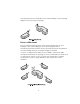
MOUNTING THE BRIDGE TO A MAST The bridge can be placed in any suitable outdoor location (see “Installation Guidelines” on page 11). Refer to the adjustable mount instruction sheet that comes with the bridge mounting hardware, and the illustrations below: Make sure that all bridges are properly oriented for polarization as described in “Polarization” on page 12. Use the polarization indicators on the antenna panel to guide orientation.
CONNECTING THE BRIDGE TO THE LAN You can connect to the LAN either through the 3Com power supply or through IEEE 802.3af power-over-Ethernet compliant equipment. USING THE POWER SUPPLY The power supply can be located indoors at any point between the bridge and the LAN access port where an accessible power outlet exists. Connect the cable coming from the bridge to the port labeled To Access Point on the power supply.
illustration shows the connection through a 3Com Ethernet Power Supply to a 3Com SuperStack® Switch. INSTALLING SOFTWARE UTILITIES The 3Com installation CD includes the Wireless Infrastructure Device Manager tool, which helps you set up and administer the wireless components of your network. It also contains documentation, including the help files for device configuration screens. To install the tool and documentation from the CD: 1 Power up the computer and insert the 3Com CD in the CD-ROM drive.
ESTABLISHING WIRELESS ASSOCIATION After the bridge and software utilities are installed, you can configure the bridge as follows: ■ Launch the bridge configuration. (See “Configuring the Building-to-Building Bridge” on page 18 for details on how to launch the configuration and make changes.) ■ For a point-to-point association between two bridges, see “Setting up an Ad Hoc Network” on page 28 and “Optimizing an Ad Hoc Installation” on page 29.
3 CONFIGURING THE BUILDING-TO-BUILDING BRIDGE If the configuration that was set at the factory does not meet your network requirements, or if you want to customize the settings, you can configure the bridge through your Web browser. The 3Com Wireless Infrastructure Device Manager helps you locate 3Com wireless LAN devices on the network, select a device and view its properties, and launch the device’s configuration in your Web browser.
identified with exclamation points (!). You can refresh this display by clicking Refresh. You should refresh the display, for example, after you change a device IP address. 2 In the Wireless Network Tree, select the device you want to configure. If more than one wireless LAN device appears in the tree and you are not sure that you have selected the right one, click Properties and check the MAC address to verify that it is the one you want. 3 Click Configure.
USING THE PRE-IP CONFIGURATION WIZARD You can only configure devices that are on the same subnet as your computer. To configure a device on a different subnet, you must first assign it an IP address on the same subnet as your computer. After you launch the configuration, you can change settings as usual. Just before you finish, you must change the device IP address back to its original setting.
2 3 4 Return to the device manager and repeat step 1 for the second bridge. Make sure that both bridges are using the same BSSID. If the bridges are not using the same BSSID, specify the BSSID on both bridges as follows: a In the Wireless Network page, select the following Network Mode: Ad-hoc (Peer-to-Peer) Specify. b Enter the BSSID in the spaces provided. c Click Save.
Property Description Device Name This name appears in the System Summary window. You 3Com Bldg-to-Bldg Bridge can change the default name to one of your choice. Device Location Optionally, you can enter a location to identify where the None device is installed. (For example, Building 4, Cubicle 3.) Help File Location ■ Web Server: Help files are located on the network at the specified Help File Path. ■ Local Drive: Help files are located on the local computer at the specified Help File Path.
To specify an IP address, click Specify an IP address, enter the IP address parameters in the spaces provided. After you change the IP address and click Save, you cannot continue to configure the device using the old IP address. To continue configuring this device after making this change, you must do the following: ■ a Close your browser. b Return to the 3Com Wireless Infrastructure Device Manager and click Refresh. c Select the device and click Configure to start a new configuration session.
To set up protocol port filtering: 1 Under System Configuration, click Protocol Filtering. 2 In the Protocol Filtering page, click the Allow radio button next to the UDP/IP or TCP/IP protocol (or click both buttons). 3 Select the Port Filtering Mode: Allow—If you want to block most protocol ports and allow a small number of others, use the Allow mode. Click the Allow radio button. Block—If you want to allow most protocol ports and block a small number of others, use the Block mode.
■ ■ To maintain wireless association, the WLAN service area on a bridge and the device with which it is associated must match exactly. Therefore, if the bridge is set to specify the WLAN service area and you change the other device’s WLAN service area, make sure to change the bridge WLAN service area also. Access Point Privacy Mode—This mode only applies when the network mode is Access Point (Infrastructure) and should only be used when access points are set with privacy enabled.
restrictions. Y indicates the power level that is set automatically; N indicates that a combination is not allowed.
■ ■ ■ ■ auto-negotiation. To enable flow control, click On. To disable flow control, click Off. Acknowledgement Delay—This setting determines the length of time the bridge waits for an acknowledgement after transmitting packets. When the delay time has passed, the bridge resends the packets. A longer acknowledgement delay allows the bridge to associate with another wireless device over a greater distance.
SETTING UP AN AD HOC NETWORK Operating in ad hoc mode, two bridges can establish a point-to-point association without an access point, allowing two LANs to communicate. To ensure correct operation, the settings on the two bridges must match exactly. To avoid the possibility of losing wireless association while you are configuring, it is recommended that you configure with a computer that is wired to the LAN. To ensure a successful association, install and configure the bridges sequentially.
OPTIMIZING AN AD HOC INSTALLATION You can optimize an ad hoc installation by adjusting antenna positions slightly to improve the radio signal between bridges. The following tools help you to optimize the installation: ■ The device manager can display a dynamic graphical representation of the bridge’s received signal strength indication (RSSI). By monitoring the RSSI while making antenna adjustments, you can ensure optimal placement.
5 6 b Enter the BSSID in the spaces provided. c Click Save. After you have enabled RSSI broadcasting on both bridges and verified that they are using the same BSSID, return to the device manager, select the first bridge, and click Properties. In the device properties window, click RSSI Monitor. The RSSI Monitor window shows a graphical representation of bridge signal strength. A value of 30 indicates good strength; a value of 40 or above is very good.
Shared key —See “40-bit Shared Key (Wi-Fi)” on page 32 or “128-bit Shared Key” on page 33. Password—If you are using a 3Com Access Point 8000, you can set up password security as described in “128-bit Dynamic Security Link” on page 33. 4 Under System Configuration, click Wireless Network. 5 In the Wireless Network page: a In the Network Mode field, click Access Point (Infrastructure). b Specify the Wireless LAN Service Area as described in “Setting Wireless Network Properties” on page 24. c Click Save.
When you are finished, click Save. Then go to the Wireless Network Properties page, set the Wireless LAN Service Area, and click Save. Security settings take effect only after you click Save in the Wireless Network Properties page. Although the bridge is allowed to associate with an access point set for a different level of encryption, data authentication is not allowed. Therefore, data cannot pass between the bridge and the access point unless their security settings match exactly.
keys in the provided spaces, then click a radio button in the Selected Key column to specify which key to use and click Save. 128-BIT SHARED KEY This option can be used with other 3Com 11 Mbps Wireless LAN devices and with equipment from certain manufacturers that also support 128-bit shared key encryption. It provides a higher level of security than the 40-bit Shared Key (Wi-Fi) option and uses a more complicated type of encryption.
settings that have already been saved. To reset the bridge, under Tools, click Reset Wireless Building-to-Building Bridge. In the next Web page, click Reset. RESTORING A BRIDGE TO FACTORY DEFAULTS You can restore bridge settings to the defaults that were set at the factory as follows: 1 Under Tools, click Restore Factory Defaults. 2 Click Restore.
To install an upgrade: 1 Use the 3Com Wireless Infrastructure Device Manager to select the device and launch its configuration. 2 Under Tools, click Upgrade System. 3 Enter the name of the upgrade file that you downloaded earlier. 4 Enter the IP address of the TFTP server where the upgrade file is located. 5 Click Upgrade. The upgrade file is copied from the TFTP server to the bridge. The bridge restarts using the new upgrade.
RESTORING A CONFIGURATION If you have stored a backup configuration on your computer, you can restore the configuration as follows: 1 Under Tools, click Restore Wireless LAN Building-to-Building Bridge. 2 In the next page, click Browse and select the backup file to upload to the bridge. 3 Click Restore. The configuration is restored and activated on the bridge. This operation may cause the bridge to reboot.
RESETTING STATISTICS LISTINGS In the Ethernet Client List page, click Reset Statistics to set the # Transmitted Packets and # Received Packets listings back to zero. CLEARING THE CLIENT LIST You can clear the client list manually by clicking Reset Clients in the Ethernet Client List page. The bridge erases the client list. Thereafter, clients are added to the list automatically when they next interact with the network.
4 TROUBLESHOOTING DIAGNOSING PROBLEMS If you have difficulty with a 3Com Wireless LAN building-to-building bridge, try the solutions in the following table. Symptom Solutions Two bridges fail to communicate in ad hoc mode. ■ Adjust the positions of the antennas to improve reception. ■ To ensure correct operation in ad hoc mode, the settings on the two bridges must match exactly.
Symptom Solutions A bridge set for 128-bit Shared Key encryption seems to communicate with an access point set for 40-bit Shared Key encryption or open system. Although the bridge is allowed to associate with an access point set for a different level of encryption, data authentication is not allowed. Therefore, data cannot pass between the bridge and the access point unless their settings match exactly. The Wireless Network Tree does not appear in the 3Com Wireless Infrastructure Device Manager window.
DISCONNECTING THE BRIDGE CAUTION: Disconnecting the bridge ends the network association. To avoid possible data loss, exit all networking applications on connected devices before you disconnect the bridge. ■ ■ ■ If you are using the 3Com power supply, unplug it from the power source. Then unplug the Ethernet cable from the power supply and the second Ethernet cable from the bridge. If the bridge is connected directly to a power-over-Ethernet device, unplug the bridge Ethernet cable from the device.
A TECHNICAL SUPPORT 3Com provides easy access to technical support information through a variety of services. This appendix describes these services. Information contained in this appendix is correct at time of publication. For the most recent information, access the 3Com Corporation World Wide Web site at http://www.3com.com/.
SUPPORT FROM YOUR NETWORK SUPPLIER If you require additional assistance, contact your network supplier. Many suppliers are authorized 3Com service partners who are qualified to provide a variety of services, including network planning, installation, hardware maintenance, application training, and support services.
Country Telephone Number Malaysia 1800 801 777 New Zealand 0800 446 398 Pakistan +61 2 9937 5083 Philippines 1235 61 266 2602 or +61 2 9937 5076 P.R. of China 10800 61 00137 or 021 6350 1590 or 00800 0638 3266 Singapore 800 6161 463 S. Korea 00798 611 2230 or 02 3455 6455 Taiwan, R.O.C. 00801 611 261 Thailand 001 800 611 2000 Or, send a description of the problem by email to: apr_technical_support@3com.com Europe, Middle East and Africa From anywhere in these regions: http://emea.3com.
Country Contact Information Asia, Pacific Rim + 65 543 6500 Phone Europe, South Africa, and Middle East http://emea.3com.com/gls + 65 543 6348 Fax For e-mail Support: http://emea.3com.com/support/email.html Central and South America http://www.3com.com/support/en_US/repair/lat.html Argentina http://www.3com.com/support/en_US/repair/lat.html Bolivia http://www.3com.com/support/en_US/repair/lat.html Brazil http://www.3com.com/support/en_US/repair/lat.
Country Contact Information Poland 00800 3111206 Portugal 0800 831416 South Africa 0800 995014 Spain 900 983125 Sweden 020 795482 Switzerland 0800 55 3072 U.K. 0800 966197 U.S.A.
REGULATORY COMPLIANCE INFORMATION 3Com Wireless LAN Outdoor Bridge Solution FCC Radio-Frequency Exposure Notice This device generates and radiates radio-frequency energy. In order to comply with FCC radio-frequency radiation exposure guidelines for an uncontrolled environment, this equipment has to be installed and operated while maintaining a minimum body to antenna distance of 2 meters. This product does not contain any user serviceable components.
Industry Canada Notice (Applicable to Use Within Canada) This device complies with Canadian RSS-210. To prevent radio interference to the licensed service, this device is intended to be operated indoors and away from windows to provide maximum shielding. Equipment (or its transmit antenna) that is installed outdoors is subject to licensing.
INDEX Numbers 128-bit Dynamic Security Link 33 128-bit Shared Key 33 3Com Knowledgebase Web Services 41 3Com Wireless Infrastructure Device Manager 18 40-bit Shared Key (Wi-Fi) security 32 A access point network 9, 30 access point privacy mode 25 acknowledgement delay 27 ad hoc network 9, 28 adapter, choosing 19 administration password, changing 35 administration tool 18 requirements 11 advanced performance properties 26 antenna aligning 12 channel and power restrictions 12 configuring 25, 27 grounding 11
E M encryption settings 31 string 32 encryption, association with different settings 32 ESSID 24 MAC address, use in locating devices 18, 19 F filtering port 23 protocol 23 firmware upgrade 34 flow control 26 G grounding antennas 11 guidelines, security 32 H help file location 22 help file path 22 hexadecimal keys 32 I installation 10 bridge 10 connecting to a wired network 15 firmware 34 power 10 requirements 10 software utilities 16 interoperating with third-party equipment 37 IP address 22 refresh
restoring settings to factory defaults 34 restrictions, channel and power 12 returning products for repair 43 RSSI broadcasting 27 S safety information 13 saving configuration changes 21 secure web server connection 22, 39 security 31 128-bit Dynamic Security Link 33 128-bit Shared Key 33 40-bit Shared Key (Wi-Fi) 32 guidelines 32 no security 32 saving settings 21 settings, radio channel 25 shared keys 32 signal strength, broadcasting 27 software utilities 16 installing 16 solving problems 38 system summar