Network Video Server User’s Manual User’s Guide FlexWATCHTM 3110 (Version. 3.0_Rev0) Seyeon Technology Co., Ltd www.flexwatch.com www.intplus.es Seyeon Tech Co.
Network Video Server User’s Manual 2 - INTPLUS [2005] - Seyeon Tech Co.
Network Video Server User’s Manual Table of Contents Overview of FlexWATCHTM Server .......................................................... 10 1 Packing List.............................................................................................. 10 2 What is FlexWATCHTM? ............................................................................... 11 2.1 Key Function of FlexWATCHTM .............................................................. 11 2.2 Product Specification .....................
Network Video Server User’s Manual 1.1 ActiveX based simple view.................................................................. 33 1.2 Java Applet based live view ................................................................ 34 1.3 Live view page guide ......................................................................... 34 2 FW-Voyager based view and recording ......................................................... 36 3 Camera configuration ...................................................
Network Video Server User’s Manual 2 PPPoE Configuration .................................................................................. 53 3 Network port configuration ......................................................................... 54 3.1 HTTP port configuration...................................................................... 54 3.2 NVCP –Tx Port .................................................................................. 54 3.3 VDCP Port configuration ............................
Network Video Server User’s Manual 3 Alarm input device connection .................................................................... 75 4 Alarm Output(Relay output) device connection .............................................. 75 4.1 Alarm output device connection........................................................... 76 4.2 Manual control of Alarm output device.................................................. 76 4.3 Automatic Control of Alarm Output device......................................
Network Video Server User’s Manual 2 Reboot .................................................................................................... 99 3 Factory Default ......................................................................................... 99 4 System Update ....................................................................................... 100 4.1 Description of files system ................................................................ 100 4.2 Update Procedure......................
Network Video Server User’s Manual Notice • The material in this document is for information only and is subject to change without notice. While reasonable efforts have been made in the preparation of this document to assure its accuracy, Seyeon Tech assumes no liability resulting from errors or omissions in this document, or from the use of the information contained herein. • Seyeon Tech reserves the right to make changes in the product design without reservation and without notification to its users.
Network Video Server User’s Manual Warning To prevent risk of electric shock, Do not remove system-case. No user serviceable parts inside. Any repair or modification for the product will be allowed to qualified service personal only. Do not expose this appliance to water or moisture. Do not install this product in Hazardous areas where highly combustible or explosive products are stored or used.
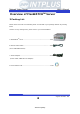
Network Video Server User’s Manual Overview of FlexWATCHTM Server 1 Packing List Please check and make sure following items are included in your package without any missing items. If there are any missing items, please refer to your local distributor. A. FlexWATCHTM 3110..…………………………………………………………………….1unit B. RS-232 Serial cable…………………………………………………………………..…1unit (Cross cable DB9 Female) C. Power Adapter…………………………………………………………………………..….1unit (Power Cable, SMPS DC 12V Adapter) D.
Network Video Server User’s Manual 2 What is FlexWATCHTM? The FlexWATCHTM server is the Network Video Server, which transmits digital images captured by Analog CCD camera over the Internet. So users can view real-time live images over the Internet at anytime and anywhere using the standard web browser such as MS Internet Explorer or Netscape Communicator. There is no need other specific software to view real-time live images over the Internet.
Network Video Server User’s Manual 2.2 Product Specification Hardware · e-mail, FTP, alarm Buffer by event or schedule · 32bit Embedded CPU · IP notification, Alarm Notification to e-mail, CGI · Flash 4Mbytes /SDRAM: 32Mbytes path by event or schedule · Hardware Motion JPEG engine PTZ & UART Control · Linux version 2.4.
Network Video Server User’s Manual · Dynamic IP support through AOIP 2.3 Basic Network Connection Diagram FlexWATCHTM server provides flexible connectivity with any type of networks available around you such as Leased line, Cable modem, xDSL line and PSTN (POT) line. Thus, it can be installed either in LAN or WAN environment as long as there is network available. But its configuration is subject to change depending on its environment. Following is basic network diagram for using FlexWATCHTM server.
Network Video Server User’s Manual 2.3.3 Dynamic IP address from Cable or xDSL line FlexWATCHTM server can be installed on even Dynamic IP network. But it needs to be registered in AOIP server which is an IP gateway running by Flexwatch.com or your local Distributor. For more details, please refer to Technical guide book in the CD manual. 2.3.
Network Video Server User’s Manual your local Phone line based Internet connection. 2.3.5 Dial-in to FlexWATCHTM server through PSTN line You can make a call to FlexWATCHTM server from anywhere and at anytime. But if you are concerned about call charge, we are recommending using above connection. 2.
Network Video Server User’s Manual B. ITS (Intelligent Traffic System) for real time monitoring C. IBS (Intelligent Building System) using FlexWATCHTM Manager D. Internet broadcasting E. School, Kindergarten, Nursery, Franchised Restaurant & convenient store. F. Facility monitoring 16 - INTPLUS [2005] - Seyeon Tech Co.
Network Video Server User’s Manual 3 Hardware Description • This chapter contains list of items to be prepared for the installation of FlexWATCHTM server. • Please carefully read this chapter before the installation. • Please prepare all the necessary items before start installation to prevent any possible malfunction or any other hazard can be happened during the installation. 3.1 Caution and observance • Keep the device in the clean and dried area where air ventilation is guaranteed.
Network Video Server User’s Manual Menu Description A DC12V DC 12V power B LAN LAN Port for 10/100M Base T Auto sensing C COM RS-232 port for serial input device, Voice kit, PTZ. Console for Hyper Terminal must be connected to this port only.
Network Video Server User’s Manual IP assignment 1 Key Words for Network LAN (Local Area Network) : Under the LAN network, any network device in the same LAN network can be accessed by any other network device. But LAN network can not be accessed from the Internet (WAN). Most of case, LAN is built after Router which is connected to WAN network so that Network device in the local area network can access to the Internet through Router.
Network Video Server User’s Manual Dynamic IP address : A dynamic IP address is an IP address that is automatically assigned to a client station (computer, network equipment, etc.) in a TCP/IP network. Dynamic IP address is typically assigned by a DHCP server, which can be a computer on the network or another piece of hardware, such as router.
Network Video Server User’s Manual LAN is never transmitted on the Internet. AOIP (Always On Internet Protocol) Server: AOIP™ server (Always On IP) is run by Seyeon Technology or its business partner and is a gateway for remote users to access FlexWATCH™ servers which is connected dynamic IP address over DSL,Cable modem and PSTN network over the Internet.
Network Video Server User’s Manual network. \ C:\> ipconfig Windows 2000/XP IP Configuration Ethernet adapter Local area connection : Connection-specific DNS Suffix . : IP Address. . . . . . . . . . . . : 192.168.0.158 Subnet Mask . . . . . . . . . . . : 255.255.255.0 Default Gateway . . . . . . . . . : 192.168.0.1 C:\> With above info, you can get information about your network from your PC and see which IP class of IP address should be assigned to FlexWATCHTM server.
Network Video Server User’s Manual Reply from 192.168.0.155: bytes=32 time=10ms TTL=128 Reply from 192.168.0.155: bytes=32 time<10ms TTL=128 Reply from 192.168.0.155: bytes=32 time<10ms TTL=128 Reply from 192.168.0.155: bytes=32 time<10ms TTL=128 2.1.2 DHCP Enabled PC If your PC is set to use DHCP, you need to check out IP address of your PC using ‘ ipconfig’ command at DOS Prompt window. You need to get IP address from your network administrator to assign it to FlexWATCHTM server.
Network Video Server User’s Manual over cable. 2.2.1 LAN Cable Environment If your PC is connected to network through LAN cable, you need to connect FlexWATCHTM server to LAN port of Hub or Router. 2.2.2 Cross-over cable If LAN network is not available, you can directly connect FlexWATCHTM server to your PC through Cross-over cable.
Network Video Server User’s Manual 2.3 PC Environment Check out whether your PC is connected to LAN or WAN network or stand-alone. If stand alone, you need to use Cross-over cable or build up LAN environment to use LAN cable. 3 Factory Default Please refer to the following factory defaults to change setting up. Factory Default Admin ID Admin password IP address Network mask root root 10.20.30.40 255.255.255.
Network Video Server User’s Manual You can use IP Installation Wizard Program through following step. (IPInstallationWizard.exe is provide in the product CD) Preset a PC with Microsoft Windows O/S. 1) Connect FlexWATCHTM server into the network (Hub) that your PC belongs to. 2) Run the IP installation Wizard program in your PC. Then following IP Installation Wizard window will show up. D A E F B G C H Description of Window Menu Description A Serial No.
Network Video Server IP Address C IP, Subnet, Gateway D ‘Set IP Address’ Button E ‘Save IP Address’ Button F ‘Go to Home Page’ Button G ‘Telnet to System’ Button H Result window User’s Manual Input an IP address to be assigned to FlexWATCHTM server Note that the IP must be directly connectable with user’s PC. The above IP ’10.10.225.100’ is only an example. Whether to change IP, Subnet and Gate or IP and Subnet mask only. To activate a new IP assignment, click this button.
Network Video Server User’s Manual 8) Click “Save IP Address” button to save IP-Address in the Flash Memory. 9) Click “Go to Home Page” button to access to FlexWATCHTM Web browser. 10) For server configuration, click “Admin” Icon and Input User ID and Password (Factory default is root : root) to get into configuration mode and then press “OK” button. ) Note Once you changed the IP address of FlexWATCHTM server, you need to connect the server with the changed IP address.
Network Video Server User’s Manual 4) Select the connected COM port with serial cable and press OK button. 5) When ‘Port Settings’ window show up, input each values from the table below. Serial Port Settings Bits per Second Data bits Parity Value 115200 8 None 29 - INTPLUS [2005] - Seyeon Tech Co.
Network Video Server User’s Manual Stop bits Flow control 1 None 6) After setting Hyper Terminal, press Enter key several times and then you can see messages as below. Input Login ID and Password. (Factory defaults for Admin ID and Password are root/root.) Seyeon Tech Co., Ltd. 2001-2003 Linux Kernel 2.4.20-syl1 FlexWATCH login: 7) If you correctly input Login ID and Password, ‘bash#’ prompt will show up as below.
Network Video Server User’s Manual Enter IP Address : 10.10.213.22 Enter Network Mask : 255.255.0.0 Enter Gateway : 10.10.1.1 Entered network configuation IP Address : 10.10.213.22 Network Mask : 255.255.0.0 Gateway : 10.10.1.1. Do you wish to apply your new network configuration ? (y/n/q): y 10) If following messages come up on your screen with “bash# ” prompt, the new network configuration has successfully applied. Your network configuration was changed.
Network Video Server User’s Manual Bash# ifconfig eth0 Link encap:Ethernet HWaddr 00:30:6F:81:00:AE inet addr:10.10.213.22 Bcast:10.10.255.255 Mask:255.255.0.0 UP BROADCAST RUNNING MULTICAST MTU:1500 Metric:1 RX packets:6382 errors:0 dropped:0 overruns:0 frame:0 TX packets:294 errors:0 dropped:0 overruns:0 carrier:0 collisions:2 txqueuelen:100 Interrupt:9 lo Link encap:Local Loopback inet addr:127.0.0.1 Mask:255.0.0.
Network Video Server User’s Manual Live view & Camera Configuration Once IP assignment is finished, you can view live view through standard web browser such as MS Internet Explorer or Netscape Navigator. There are two different type of viewing option provided by FlexWATCHTM server. One is simple live view and the other is “FW-Voyager” which provides personal Network DVR(Digital Video Recording) and viewing solution. Depending on the OS and web browser, you can get different viewing option as well.
Network Video Server User’s Manual When the Client pc is not connected to Internet, you need to manually install ActiveX components in your viewing PC. - Insert the product CD in your PC - Select “FlexWATCHTM Simple Viewer control” program - Application idea ActiveX based SDK is provided for software developers so that application program developers can easily utilize digital video from FlexWATCHTM server for his own video application. 1.
Network Video Server User’s Manual screen, snapshot, PTZ control, Relay output control, Voice kit connection as well. Cam Control : By checking the camera you can get any number of camera displayed on the same screen. Camera 1, 2, 3, 4 and all cameras can be displayed together. Sequence : To view camera selected camera sequentially. Frame rate : You can adjust display frame rate by control Frame rate option Display size : X1 for Real size, x2 for double size and Full screen mode is supported.
Network Video Server User’s Manual Output control : Relay output device can be controlled through simple view page. But note that you need to get permission to control it. 2 FW-Voyager based view and recording FW-Voyager is web based DVR software for personal video recording. Using this free software, user can easily install the software and do video recording at any time. Note that FW-Voyager is works on MS Internet explorer of Window OS.
Network Video Server User’s Manual video related value string for his own application. Default Video Format : To manually change video format.
Network Video Server User’s Manual Thus, please contact your local vendor to get more in-depth technical info to decrypt the value string. 3.1.1 Image encryption Image encryption is security feature to prevent unwanted image hacking when anonymous user accesses the system. Once it is enabled, user must enter encryption code to view live video. 1) Simple set up encryption code 2) Enter encryption key code to view live. Up to 8 alpha-numeric characters can be used.
Network Video Server User’s Manual User defined camera name will be appeared on the camera name column of video. Up to 20 different English characters can be used. ( Notice : If you are using 2-Byte Unicode Character, number of character is limited to 10 ) Image Size : 4 different size of video can be set up.
Network Video Server User’s Manual displayed. Video Source: color and Gray mode option Image Quality: 5 quality levels - highest, high, normal, low, lowest ) Note Please note that if you increase image size and quality, actual JPEG file size will be increased and this may affect actual transmission frame rate. Thus, you are required to check out your network bandwidth available for FlexWATCHTM server and select the right size and quality of video.
Network Video Server User’s Manual 3.3.2 How to save Motion triggered image in the NVR solution Recording in the FW-5440/5000 Simply check “Motion Detection” option in the recording condition menu in the FW5440 or FW-5000 when motion detection option is enabled in the FlexWATCHTM server. 41 - INTPLUS [2005] - Seyeon Tech Co.
Network Video Server User’s Manual Recording in the FW-Manager To record motion triggered image in the FW-Manager (NDVR Software) client program, you should not use Software motion detection function in the FW-Manager. - Simply configure motion detection for the selected camera in the FlexWATCHTM server - Set up Motion based recording condition in the FW-Manager (Do not set up motion detection area in the FW-Manager software). 42 - INTPLUS [2005] - Seyeon Tech Co.
Network Video Server User’s Manual System Configuration System configuration is to set up basic functions which help you properly run and manage the system. It is highly recommended to set up the configuration before any other configurations. Following functions are provided in the System configuration mode.
Network Video Server User’s Manual 1) Go to Date & Time setup menu in the System configuration section of Admin mode 2) Set the correct time and click “Apply” button 2.2 Date & Time using NTP server If multiple servers are installed over the network and controlled by client program and synchronized time info is required, use NTP(Network Time Protocol) option. 1) Go to [NTP setup] menu in the Network configuration section of Admin Mode 2) Type in NTP server name or use default NTP timeserver, ntp.ewha.
Network Video Server User’s Manual A. Option to allow system access without system Login ID & PW B. Channel based different user account creation C. Different control authority for Video, PTZ, Audio, and relay output device control 4.1 Full Access To allow system access by anyone who know the IP address. PTZ, Audio and Relay output device can be controlled by anyone. Thus, if security for video is important, it is highly recommended to user limited access mode below 4.
Network Video Server User’s Manual Full Access : If full access is selected, any body can access the server and control the video. No Access : This is to temporally restrict camera access by specific user without delete user account to temporally block access to the camera. Selective Access: This is to set up control authority for the respective or all cameras. VS Module ID is FlexWATCHTM server ID which is recognized by the server. Default # is 0.
Network Video Server User’s Manual Thus, 4TH camera can be Camera# 3 in this menu. 5 Frame rate control Maximum Video frame rate which sever can transmit over the IP network can be set up through Frame rate control option. Through this maximum frame rate control option, user can limit network bandwidth consumption by video transmission. 1) Go to [Access Control] option in the system configuration menu in the Admin page. 2) Set up Maximum frame rate. Following table could be an example.
Network Video Server User’s Manual 6 Tx Module Registration(NVCP) ) - Notice If you do not connect FlexWATCHTM server to NDVR server, do not set TX module configuration - Once Tx Module configuration is done, set up RX module configuration in the NDVR server as well Video proxy function is supported by NDVR server such as FW-5440 and FW-5000 server.
Network Video Server User’s Manual 1) Click TX Module registration menu in the System configuration mode of Admin window. 2) Type in NVCP Password in the NVCP Password configuration filed. ) Notice NVCP Password is security feature which authenticate server access by RX module (FW-5440 or 5000 NDVR server) to FlexWATCHTM server. Once NVCP Password is configured, that password must be set up in the NDVR server to get video from FlexWATCHTM server. Thus, you must make a note of NVCP password.
Network Video Server User’s Manual 5) Once Active mode is selected, type in IP address of NDVR server.
Network Video Server User’s Manual Network Configuration Network configuration mode provides interface for the server to be connected to broadband network or PSTN line. In addition to basic network, application port such as HTTP, NVCP, Voice port configuration and IP filtering options are provided. 1 Network configuration You can change IP address of server through LAN configuration mode. 1.1 Static IP Select this to assign static IP in the server.
Network Video Server User’s Manual Once DHCP is enabled, there is not other setting to be changed in the network works configuration except DNS info, if required. 2.1.1.1 IP notification by E-mail service You can receive IP address of the server through e-mail from the server, when the server is connected to DHCP server. Please do not enable DHCP client feature till you open a way to receive or get IP address of server. 1) Check whether you are in the DHCP environment before starting set-up.
Network Video Server User’s Manual configuration in Advanced Service 2.1.1.1 Server access through AOIP server Once Server is registered in the AOIP server and DHCP is enabled, you can access the server through AOIP server. IP address of server can be found from AOIP server as well. In this case you do not need to configure e-mail address setting to get IP address from the server.
Network Video Server User’s Manual Once PPPoE is enabled, LAN network setting will be disabled. 3 Network port configuration HTTP port, NVCP and VDCP ports are application port through which video and audio data can be transmitted over the TCP/IP network. 3.1 HTTP port configuration When you need to change Default HTTP Port (#80) to other port, you can change HTTP port. This is very useful when more than one server should be installed behind a router.
Network Video Server User’s Manual Note that when Voice Kit is connected to Internet, respective UDP port of the router must be opened. 4 WAN Configuration and Application Server is designed to make a call to ISP or can receive a call from outside so that server can establish Internet connect to send FTP, e-mail or send video & data through PSTN line or other medium. This is best alternative when the broadband Internet access is not available. 4.
Network Video Server User’s Manual Server can establish the Internet connection through PSTN line and send FTP or e-mail when the alarm condition is triggered by any event.
Network Video Server User’s Manual PPP Client : This means that FlexWATCHTM server act as client and call out to ISP.\ PPP Server : This means that FlexWATCHTM server acts as a Server and receives a call from remote user. Tel#, User ID and User password : ISP phone number and user account for Internet connection to ISP. Default Route : Enable this option. When Dial-out option is selected. ) Note If you use external modem, we recommend ‘3COM U.S.
Network Video Server User’s Manual modem, GSM or GPRS Modem or any type of wireless modem. This mode is not for general users. Thus, if you need to connect special modem device, please contact your vendor or manufacturer for more information, sales@flexwatch.com 4.4 Dial-in Configuration Dial-in is to allow client PC to call into the server and get live video through PSTN line. Overall configuration is very similar to that of Dial-out configuration. But much more simple than Dial-out.
Network Video Server User’s Manual of the FlexWATCHTM server. Local IP address and Remote IP address is virtual IP address which is used at the time of Modem connection only Local IP address : System default IP address (192.168.2.1) resides in the FlexWATCHTM server for modem connection only. So when you connect the FlexWATCHTM server from remote PC using dial-up networking and physical connection is made, you need to run your web browser and enter this system default IP address(192.168.2.
Network Video Server User’s Manual LAN : This is default path the send any data to outside. Modem : when PSTN or other medium than LAN is used to send data to outside. This service port must be checked when any data is to be sent through PSTN or other medium than LAN which is connected to COM port. ) Note Service path must be set up and checked before starting WAN configuration to send any data through external PSTN modem connection or equivalent If LAN is to be used, select “None(LAN)” option.
Network Video Server - User’s Manual Once things are set up, you can login to AOIP server and connect your FlexWATCH™ server. ) Note AOIP is proprietary data service run by FlexWATCH™ or its business partners around the world. Thus, depending on the country AOIP service can run by your local vendor or master distributor or in some case, you need to user AOIP server run by manufacturer. More detailed information about how to use can be acquired by contact your local distributor or sales@flexwatch.com .
Network Video Server User’s Manual NVCP-Tx Port should be enabled only when video is transmitter to NDVR server such as FW-5440 and FW-5000, or Video proxy server supplied by FlexWATCHTM server. If not, do not enable this option. 7 Network Status You can see all the network status configured in the system through “Network status” option. Please Select “Network Status” menu in the Network configuration mode of Admin Window. 62 - INTPLUS [2005] - Seyeon Tech Co.
Network Video Server User’s Manual External Device connection & configuration External device such as Serial input device, Serial output (UART) device, PTZ (pan/Tilt/Zoom) device, Audio kit and Alarm input and output device can be connected to the system and controlled over the TCP/IP network. 1 Serial Ports Configuration Guide This chapter will guide you how to install and configure Serial-interface devices.
Network Video Server User’s Manual Available Devices COM AUX Console (Hyper Terminal) O X Modem X O PTZ O O Voice O O Serial Input O O Serial Output O O None O O 1.1.2 Ports Connection for using two different devices. AUX and COM part is provided for RS-232 and RS-485 or RS-422 connection. This enables user to connect more external devices to the server and selectively use them per 64 - INTPLUS [2005] - Seyeon Tech Co.
Network Video Server User’s Manual his needs. But same type of port for RS-232, RS-485 or RS-422 can not simultaneously be used. For example, if COM part of RS-232 is used by Hyper Terminal Connection, COM part of RS-485 can not be operative. In this case, AUX part of RS-485/RS-422 or RS-232 port should be used. Interface combination Ports Connection RS-232 + RS-232 RS-485 + RS-485 RS-485 + RS-422 RS-422 + RS-422 65 - INTPLUS [2005] - Seyeon Tech Co.
Network Video Server User’s Manual RS-232 + RS-485 AUX(RS232) and COM(RS485) or COM(RS232) and AUX(RS485) RS-232 + RS-422 AUX(RS232) and COM(RS422) or COM(RS232) and AUX(RS422) ) You cannot make use of AUX (RS232) port and AUX (RS485, 422) part at the same time. Also it is not available to use of COM (RS232) port and COM (RS485, 422) part together. 2 Installation & Configuration of External Device 2.
Network Video Server User’s Manual 3) Select ‘Console’ at COM mode, and Click ‘Apply’ button 4) System reboot will be recommended, then click ‘Reboot’ button. 2.2 Serial Input device Serial input device such as Car Speed sensor, BOG sensor, POS (Point of sales), ATM device which communicate with external device through RS-232 port can be integrated with the system. And that data can be transmitted along with video to anywhere over the TCP/IP network.
Network Video Server User’s Manual only. This function is not for general use. Thus, if you need more close information about this, please contact your local distributor or manufacturer for further information, sales@flexwatch.com. 2.3 Serial output device The system supports to relay third party command to target device through Serial output device control mode. Through this, user defined message can be reached to target device The system supports two different modes.
Network Video Server User’s Manual G. After setting up the parameters in the each filed, click ‘Apply’ button. Note that if you are using X10 device protocol, you do not need to set up parameters, but simple select X10 “Enable” option. 2.3.2 X 10 device & Z256 X10 and Z256 is a protocol name of Device which is to control electronic devices over the Power line communications.
Network Video Server User’s Manual A. By-pass command string from third party This is to send command string from third party application program to the target device connected to the server. More about this function can be supplied by HTTP CGI API guide. B. Control panel inside of the system You can create control panel of external device inside of the server and control target device through server web page. This function is not for general use.
Network Video Server User’s Manual 2) Go to Admin Menu >> System Configuration >> Serial Ports Configuration. 3) Select ‘PTZ’ at COM or AUX mode, and click ‘Apply’ button. 4) System reboot will be recommended, then click ‘Reboot’ button. 5) After rebooting, Go to Admin Menu >> System Configuration >> Serial Ports Configuration. 6) Click “PTZ Mode”, then following window will show up 7) Select the installed PTZ Model on the dropdown menu as above.
Network Video Server User’s Manual Lab Test Field Test O O O O O O Auto PAN Model Comman d Preset Spectra 485 (P) ** Pelco Spectra 485(D) * Panasonic WV-CS854 485 O ** AD Delta Dome 485 O * Samsung Techwin SPD1600 485 O O * Samsung SCC-641 485 O O Seyeon FSD-230 485 O Seyeon SPT-101(2) 485 SRX-500 485 CANON VC-C4 * VICON Supplier ** Pelco Program Only O O O O O O O O O O O O 232 O O V-1311 485 O O ***VICON Surveyor 485 O KALATEL Cyber
Network Video Server User’s Manual RNK RNK-DOME 485 DAIWA DMP-23-H1 485 LILIN PIH-717 485 PHILIPS Auto Dome 485 FINE system CRR-1600I 232 O O O Samsung Techwin SRX-100B 485 O O O O O O O O O O NOTE : Symbol Reference * : Preset function was program only. ** : Preset function was Lap Tested only. *** : Preset function was field Tested 2.5 Voice Kit Connection and configuration G.723.
Network Video Server User’s Manual 5) System reboot will be recommended, then click ‘Reboot’ button. 6) After rebooting, Go to Admin Menu >> System Configuration >> Serial Ports Configuration 7) Click “Voice Mode”, then following window will show up UDP Port : Voice kit use UDP port to transmit Voice kit. If voice communication should be done through WAN network, please make sure UDP port is not blocked to Internet connection in router or firewall etc.
Network Video Server User’s Manual 8) Click “Save” button to save your configuration. 3 Alarm input device connection FlexWATCHTM server has Alarm Sensor interface so that it can send alarm notification by activating e-mail or FTP function or activate alarm output device such as Siren or light. FlexWATCHTM server supports opto-coupled input circuit and any dry contact type of Alarm sensor can easily be interfaced to the server. Following is circuit diagram for Alarm input part.
Network Video Server User’s Manual light. Manual or automatic control of alarm output device is supported by the server so that relay output device such as siren, light or any output device can remotely be controlled through standard web browser or third party application program. 4.1 Alarm output device connection Any Relay contact type of output device can be interfaced with FlexWATCHTM server. Simple connect the Alarm output device to Relay output(DO) port of FlexWATCHTM server.
Network Video Server User’s Manual 3) Check the output port number and click apply button to activate the alarm output device 4.2.2 Alarm output device through Admin Page Alarm output device can manually be controlled through Admin page of the system. This option is recommended when web browser based alarm output control panel is hided and administrator want to manually control Alarm output device.
Network Video Server User’s Manual combination is provided so as to set up powerful and various working condition for each alarm output device. 1) Go to Advance service option in the Service configuration mode in the Admin window. 2) Click None buffering service menu and select “Alarm output” menu. 3) Check the service “Enable” option and select output port 4) Select Alarm Duration time from the drop down menu.
Network Video Server User’s Manual Advanced Service configuration Advanced service configuration is intended to provide more sophisticated functions which are required by sophisticated users. Thus, if you are not familiar with or not good at advanced features, we recommend you to read this guide carefully and consult with your local vendor to get more close information about these features.
Network Video Server User’s Manual & ftp and Alarm buffering service B. Pre alarm buffer size : Once memory allocation is done, assign Pre alarm buffer size (Pre alarm image buffer pool) to be used for e-mail, FTP and Alarm buffering services. Any pre alarm buffer for respective e-mail, ftp and Alarm buffering services can be done within Pre alarm buffer size. C.
Network Video Server User’s Manual pre alarm buffer size for respective camera can be done within this assigned memory. Note that Pre Alarm buffer for even Alarm buffering service can be done within this memory size. Thus, you need to be careful to assign memory for this service.
Network Video Server User’s Manual maximum number of pre alarm for e-mail, ftp or Alarm buffering service (Pre alarm only) can be done with this buffer size, if there is enough memory space for respective services. Note that there must be enough memory space left for e-mail, ftp and Alarm Buffering service (Pre alarm only), since respective service (e-mail, ftp or Alarm buffering service) consumes separate memory in addition to pre alarm buffer size configured to make a real service.
Network Video Server User’s Manual Alarm buffering service size (60%) • Total Buffer size is variable depending on the memory used by the system - Total number of Pre Alarm+ Post Alarm for FTP per channel < 256 frame. - Total number of Pre + Post alarm for e-mail per channel <10 frames for channel. - Pre alarm frame for FTP & e-Mail and Alarm buffer service shall be done within Total pre-alarm buffer size - Post alarm for FTP & e-mail has nothing to do with Total buffer size.
Network Video Server User’s Manual 2) Go to Buffering service mode 3) Click “Buffer Calculator” button to run the calculator 4) Pre configure pre/post alarm buffer for each service. This previous window can be open till you manually disclose the Window. Thus, you can refer to this table when you configure e-mail, ftp or Alarm buffering service configuration. 2 Service Condition Sophisticated advanced services can be done by lots of serviced conditions provides by the system.
Network Video Server User’s Manual Condition Setup Criteria Set up 2.1 Condition Setup This is to define basic condition to activate any option selected. Select right condition from the option provided. Always : To active any selected option regardless condition. If you select this condition Schedule and Event condition window become inactive. Schedule Only : To active any selected option by scheduling. If you select this criteria, Event condition 85 - INTPLUS [2005] - Seyeon Tech Co.
Network Video Server User’s Manual setup window become inactive Event Only : To activate any selected option by Event only. Sensor status change is recognized as Event. Schedule and Event : To active any selected action when Event is triggered for the specified time period only. If Event is incurred out of Scheduled period, no action will be done. 2.2 Criteria Setup Once condition is selected, you need to set up event criteria following which any selected service will be executed.
Network Video Server User’s Manual Event number can be mapped as a Sensor port and camera number. DI Open State : This means that sensor is triggered and become open status from Normal close status. Select this when you use NC(Normal Close) type sensor. DI Close State : This means that sensor is triggered and become close status from Normal open. Select this when you use NO (Normal Open) type sensor. Motion Detection : By selecting this option, motion detection based event can be configured.
Network Video Server User’s Manual 3 e-mail configuration Schedule, event or schedule and event driven e-mail sending is supported by the server so that when there is any pre-configured event is happened, e-mail notice will be sent to any e-mail account. 3.1 e-mail function configuration Up to 10 pre/post alarm image can be appended and sent through one e-mail when the event happens. By configuring pre/post alarm for e-mail, you can decide the number of image to be sent by an e-mail.
Network Video Server User’s Manual Authentication Login: Now these days most of ISP is try to authenticate sender e-mail address due to security and spam mail issue. If sender authentication is enabled by your ISP, you need to get your login ID and Password from your e-mail service provider. Sender (E-MAIL): put the sender e-mail. If you use system default sender e-mail address, it will not work. E-mail address 1~ 3: put recipient e-mail address. Up to 3 different e-mail account can be supported.
Network Video Server User’s Manual with Pre alarm buffer size. Note that the sum of pre and post alarm can not exceed 10 frames. Value Format : Value strings can be sent together with e-mails. Please click “ ” mark in the admin page to get more information. 3.2 e-Mail condition set up Up to 3 different e-mail conditions can be set up for each camera. Schedule, event or schedule & event driven e-mail condition can be set up to send e-mail.
Network Video Server User’s Manual slightly different. 4.1.1 Directory option for Buffered FTP Buffered FTP means that only pre/post alarm buffered image will be sent to FTP server when the ftp is triggered by the event. FTP function of FlexWATCHTM server has two different level of directory and file name option and following are details. Base Directory Name : Base directory is a path where ftped image will be saved in the FTP server.
Network Video Server User’s Manual User defined prefix of file name of each image. File name of FTP images will automatically be concatenated after prefix( Base File name ). Directory name : Multiple directories can be created in the Base directory so that ftp image can be stored in a classified directory. Once you select Directory name filed and click “Make Directory” button, multiple subdirectories will automatically be created in the Base directory according to selected option.
Network Video Server User’s Manual limit number of image to be stored and refreshed. If you set it as 8, 8images will be stored in the FTP directory and FIFO(first come, first out) based image will be saved in the FTP server. Overwrite: This is to refresh old image with new image in the ftp server. This is normally used when the ftped image should be refreshed every time. 4.
Network Video Server User’s Manual 1) Go to Advance Service menu in the service configuration mode and select Buffering Service option 2) Set up Pre alarm buffering configuration for FTP service 3) Set up FTP directory and file name option 4) Select the camera and set up FTP condition for each camera. Up to 3 different ftp condition can be set up for each camera. 4.2.2 Periodic FTP service Periodic FTP means that image will continuously be sent to FTP server when there is any event.
Network Video Server User’s Manual 4) Go to ‘Advanced Services’ menu. - Click ‘Apply’ button to apply the new service configuration as above. - Close the window of ‘Admin menu’. When ‘Save configuration’ window pop-up, click ‘Save Configuration’. Application idea If server is connected to dynamic IP or Private network and you want to continuously send image to FTP server, please use Overwrite function in the Periodic FTP service.
Network Video Server User’s Manual 4) Enable the Alarm buffering service. 5) Select the camera and assign Pre/post alarm image frames. 6) Click “Save” button to memorize your new setting in the system. 7) Click the Condition menu and set up alarm buffering service condition. 8) Click “Advance Service” menu in the Admin window and click “Stop and Apply” button to start record alarm triggered image in the system memory.
Network Video Server User’s Manual Preview Single Images: This is to view image one by one. Preview Multi images: You can view panoramic images of all the saved images at a glance. 2) Click Preview Single Imager or Preview Multi images option to playback.
Network Video Server User’s Manual program through CGI Patch. This option is to invoke third party application program upon receipt of sensor information from FlexWATCHTM server.
Network Video Server User’s Manual Utilities Utilities is to manage and control system properly. Save Configuration, Flash Update, System Reboot and system upgrade options are provided. 1 Save Configuration This is to save all new configuration and settings in the system memory. Once new configuration is saved by “Save Configuration” menu, new configuration will permanently saved in the system memory only after system Reboot or system power off 2 Reboot Reboot means restart system.
Network Video Server User’s Manual logics for system configuration, since executing this option Except Network configuration will lose all of your setting. 4 System Update System update can remotely be done through web page of the system or ftp option with telnet and Hyper Terminal mode. In this user manual only web based system update method is described and ftp based system update method can separately provided. 4.
Network Video Server User’s Manual All (kernel, RAM disk, System, Web) Update: To completely update all the system for Kernel, RAM Disk, System and Web all together except PTZ Device Driver or Sensor Device Driver. This option is recommended if there is special notice by manufacturer. Generally complete system update comes only when there is big change for all of the system software. System and Web Update: To update system and web related software together. This update can be common to update the system.
Network Video Server User’s Manual PTZ Device Driver : PTZ Device Driver is already built-in the system. But if there is a new PTZ Device driver supported by the system, it can separately uploaded into the system without other software change. Sensor Device Driver : Serial input device driver can separately be uploaded into the system so that independent Serial input device can work with FlexWATCHTM Server. 4.
Network Video Server User’s Manual 4) Once update is successfully done following result will come up. 5) If you want to update RAM Disk, System and web page, please click “Next” button follow the web guide to update more files. 6) If all of file update is finished “System Reboot” window will come and do system reboot to apply new update. 103 - INTPLUS [2005] - Seyeon Tech Co.
Network Video Server User’s Manual 104 - INTPLUS [2005] - Seyeon Tech Co.
Network Video Server User’s Manual Warranty Product Network Video Server Model S/N FlexWATCHTM 3440 A/S Seyeon Tech Ltd. +82-2-3017-0866 1 year Limited www.flexwatch.com Warranty Seyeon Tech Co., Ltd. TEL : +82-2-3017-0855 FAX : +82-2-3017-0843 http://www.seyeon.co.kr http://www.flexwatch.com A/S Center: Tel : +82-2-3017-0855 Fax: +82-2-3017-0843 105 - INTPLUS [2005] - Seyeon Tech Co.