
Installation Instructions


Router 3033 17
Router 3033 The following illustrations depict the components of the Router 3033.
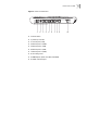
Figure 7 Router 3033 Front Panel
■ 1. ETH LED (LAN3)
■ 2. ETH LED (LAN2)
■ 3. ETH LED (LAN1)
■ 4. ETH LED (LAN0)
■ 5. G.SHDSL active LED (DSL ACT)
■ 6. G.SHDSL link LED (DSL LNK)
■ 7. System LED (SYS)
■ 8. Power LED (PWR)
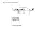
Figure 8 Rear panel of Router 3033
■ 1. Power switch
■ 2. Power input socket
■ 3. Console port (CON)
■ 4. Ethernet port 0 (LAN0)
■ 5. Ethernet port 1 (LAN1)
■ 6. Ethernet port 2 (LAN2)
■ 7. Ethernet port 3 (LAN3)
■ 8. Grounding screw
1
2
3
4
5
6
7
8
1
2
3
4
5
6
7
8
9