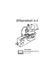
User guide Before using the machine, read this user guide thoroughly and make sure that you have understood it.
CONTENTS CONTENTS ......................................................................... 2 GENERAL ........................................................................... 3 DESCRIPTION OF FIELD OF APPLICATION.................... 3 SYMBOLS ........................................................................... 4 WARNING STICKERS ........................................................ 4 SAFETY REGULATIONS.................................................... 5 MOTOR DATA - Sliprobot L1 .............
GENERAL This user guide describes in detail how to use, maintain and inspect the chain sharpening machine. It also describes the steps to be taken to ensure maximum safety, how the safety components are designed and how they work and how to check and inspect them. It also explains how to carry out any repairs that may be needed. NOTE: Everyone who will install, use or repair the chain sharpening machine must read and understand this manual.
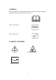
SYMBOLS Before using the chain sharpening machine, read this user guide thoroughly and make sure that you have understood it all. Wear eye protection. Wear safety gloves. WARNING STICKERS Caution Risk of cutting injury.
SAFETY REGULATIONS Locate the machine where it is not exposed to rain or moisture. The site must be well lit. The machine must not be located close to gas, liquids or other materials that might catch fire or explode. Only a service technician is permitted to carry out work on the machine. To avoid mistakes when sharpening chainsaw chains, it is extremely important to understand how the sharpening machine works. Read the instruction manual carefully before doing any sharpening with the machine.
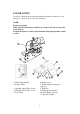
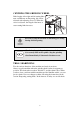
POWER SUPPLY In order to obtain the best result the machine should be connected to a car battery 12 volt (max 12-14 volt, min 9 ampere). NOTE: Battery placement. Make sure that the battery terminals are connected to the correct poles of the battery. Position the battery so that sparks from the sharpening machine cannot reach it. 1 2 3 4 11 10 9 1. Sharpening machine 2. Battery cables 3. Grinding wheel 150 x 4 x 16: 4. Grinding wheel 150 x 4 x 16: 5. Stop clamp 8 7 6 5 6. Profile stone 7.
Machine operating controls 1. Start the motor of the sharpening machine. 2. Start the automatic system. 4. Electric power (12-14 V DC) in. 5. Stop button. (zero-voltage cutout. When the power is cut off, the machine must be started manually.) 7. Power on. 12. Chain rulers. 13. Adjusting the grinding angle 0°- 35°. 14. Grinding wheel. 15. Grinding motor. 16. Depth adjustment of the grinding wheel. 8. Stop clamp 17. The graduated scale shows grinding angles from 90° to 50°. 9.
INSTALLING THE SHARPENING MACHINE The machine must not be located close to gas, liquids or other materials that might catch fire or explode. Install the machine on a bench or stand. NOTE: The machine must be securely fixed. 1 The machine should be mounted so that the front edge of it reaches 1-5 mm over the edge of the bench or stand.
CENTRING THE GRINDING WHEEL If the lengths of the right and left cutting links turn out different on sharpening, this can be adjusted with adjusting screw 11. When the screw is adjusted, the length of the inner or outer cutting links increases. 0 0 15 5 1 5 25 30 3 11 Be ready to stop the machine if something goes wrong during trial sharpening. Check that the grinding wheel is not cracked and that it is securely fixed to the spindle. Stop the grinding wheel immediately if abnormal vibrations occur.
SHARPENING CUTTING LINKS Always wear safety gloves when handling saw chains. Risk of cutting injury. With manual or automatic shoutdown. The machine can be stopped manually without a stop clamp when sharpening is complete, or with a stop clamp as described below. Activate Power on, switch 7 Start grinding motor only with switch 1. Using profile stone 7, profile the grinding wheel for the type of chain to be sharpened, as shown in Figure H. Check with profile template 6.
FOR A DOUBLE LINK, PROCEED AS FOLLOWS Sharpen the other (2) (Fig E) of the two links on the same side, double links 2.3. Stop the automatic system with switch 2. Fix the clamp 1 (Fig F) between the two double links 2.3. Start the automatic system with switch 2 and the motor with switch 1. Let the machine run one revolution to clamp 9 (Fig. F). Stop the machine using the stop arm 20.
SHARPENING SETTING Setting the stroke between the cutting links. (Slacken the wingnut and push it to the right for a shorter stroke.) Adjust the cutting tooth length setting. (Clockwise = shorter cutting tooth) Depth adjustment of the grinding wheel. (Anticlockwise=deeper grinding into the cutting tooth).
GRINDING THE DEPTH GAUGE LUGS The incoming power must always be switched off. Set the grinding angle (o° degrees); see under Grinding angle. Check that the grinding wheel is not cracked and that it is securely fixed to the spindle. Stop the grinding wheel immediately if abnormal vibrations occur. Install the correct grinding wheel 1 (Fig G) for grinding the depth gauge lugs (6 mm). Profile the grinding wheel so that it matches the lugs 2. Adjust 3 back so that the grinding wheel 1 is aimed at the lug 2.
MAINTENANCE CHANGING THE GRINDING WHEEL The incoming power must always be switched off. 1. Lift up the grinding head (1) and remove the guard (9). 2. Hold the grinding wheel (2) and slacken the nut (3) manually or with pliers. 3. Remove the old grinding wheel and fit the new one.
SETTINGS AND SERVICING The incoming power must always be switched off. If one cutting link gets too deep or too shallow, this can be changed by slackening screw 1, 2, 3 or 4 and turning motor 5 as shown. Turn the motor in the relevant direction and tighten the screws. The machine is largely maintenancefree, but it should be kept clean by removing any grinding dust. A = Deeper grinding on this cutting link. B = Deeper grinding on this cutting link.
TROUBLESHOOTING The incoming power must always be switched off. The chain is not fixed during sharpening (Fig. I). Tighten M6 nut (1) clockwise about one turn, or more if necessary. More thorough servicing or troubleshooting must be done by the dealer’s servicing team.
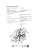
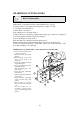
25 1 24 2 3 4 5 23 21 6 20 22 19 14 16 17 15 18 13 12 11 15 8 10 7 9 17
2 3 4 13 11 12 1 10 5 9 8 7 8 18
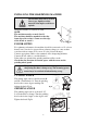
EC DECLARATION OF CONFORMITY Manufacturer: Markusson Development Systems AB Tegelbruksvägen 762 31 Rimbo, Sweden hereby declares that: Sliprobot L1 Logosol Sliprobot L1 has been manufactured in compliance with the following EC directives: 98/37 EC, The Machine Directive 73/23 EEC as amended, The Low-Voltage Directive 89-336/EEC as amended, The EMC Directive The following standards were used as a basis for this declaration.
Basic tips: Cutting angle, see page 8 in the operator's manual. In most cases we recommend to grind at 60 degrees or from 50 to max 75 degrees. This also applies if the chain manufacturers recommend other settings. Sharpening settings, see page 12 in the operator's manual. The stroke length setting is changed by loosening the wing nut. Now slide the plate that controls the stroke length so that the front feeder arm falls down approximately 2 mm behind the cutting tooth to be fed forward.