1 Mbps bps Wireless LAN Acce ccess Point 8000 U se r G u i d e Version 1.0 http://www.3com.com/ http://support.3com.com/registration/frontpg.pl/ Published January, 2002 Version 1.
3Com Corporation Copyright © 2002 3Com Corporation. All rights reserved. No part of this documentation may be reproduced 5400 Bayfront Plaza in any form or by any means or used to make any derivative work (such as translation, transformation, or Santa Clara, California adaptation) without written permission from 3Com Corporation.
CONTENTS 1 INTRODUCTION Setting up a Wireless Network 1 Wireless and Wired Networks 1 Network Security and RADIUS Support AP8000 Feature Summary 2 Installation Overview 3 Software Utilities 4 2 1 INSTALLING THE ACCESS POINT Before You Begin 5 Deciding Where to Place Equipment Connecting the Standard Antenna Placing the Access Point 7 Mounting on a Wall 7 Mounting on a Ceiling Connecting Power 6 6 8 9 Connecting to an Ethernet Network Checking the LEDs Antenna Options 10 10 11 Omnidirectio
Using the Configuration Management System System Configuration Access Point Properties Network Properties 22 22 Data Transmission Properties Security 23 24 AP Encryption 24 User Access List 25 RADIUS Authentication and Accounting Management TFTP Setup 26 26 System Log Setup 26 27 Upgrade System 27 Downloading Upgrade Files Installing an Upgrade 27 27 Change Administration Password Configuration Backups Statistics 27 28 28 System Status 29 Restoring an Access Point to Factory Def
INDEX REGULATORY COMPLIANCE INFORMATION
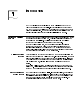
1 INTRODUCTION The 3Com wireless product family lets you set up a local area network (LAN) without the restraints of network cabling. If your office already has an Ethernet LAN, the 3Com 11 Mbps Wireless LAN Access Point 8000 can extend the network without additional cabling. The access point security features will also extend the security of installed wired networks to include all wireless components.
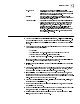
2 CHAPTER 1: INTRODUCTION The security configuration options include: Authentication Encryption Description 802.11 standard No encryption Basic area network name with no encryption. 40-bit shared key Standard WiFi Requirement to insure Open 802.11 standard 40-bit shared key 802.11 standard interoperability. 128-bit shared key 128-bit shared key Strong encryption. Compatible with other vendors' 128-bit shared key scheme including AirConnect, Agere, and Cisco.
Installation Overview 802.1x Support 3 Port-based network access control utilizes the physical characteristics of the switched LAN infrastructures to authenticate devices attached to a LAN port, and prevent access to that port in cases where the authentication process fails. Encryption Supports 40-bit and 128-bit shared encryption, and 128-bit dynamic encryption key.
4 HAPTER 1: INTRODUCTION C Software Utilities The 3Com Administrator Utilities CD includes tools and utilities to help you set up and administer the wireless components of your network. Software tools and utilities are presented as Tools and Utilities options on the main menu of the CD and include: ■ Install the Utility Software and Documentation.
2 Before You Begin INSTALLING THE ACCESS POINT The following items are required for installation: ■ ■ 3Com Integrated Power-over-Ethernet power supply and power cord. Standard category 5 straight (8-wire) Ethernet cable for connecting the access point to the power supply. This length of cable must reach from the access point to the power supply. If you plan to connect the access point to a wired network, you will need an additional length of Ethernet cable.
6 CHAPTER 2: INSTALLING THE ACCESS POINT Deciding Where to Place Equipment Select a clean, dry location that provides good reception. The site should not be close to transformers, heavy-duty motors, fluorescent lights, microwave ovens, refrigerators and other equipment. If you are connecting the access point to a wired network, the location must provide an Ethernet connection. The power supply also requires an Ethernet connection, and in addition must be located near a power source.
Placing the Access Point Placing the Access Point 7 The access point can be placed on a flat surface such as a table or desktop or it can be mounted on a wall or to theT-rail grid of an acoustical ceiling. If you choose a flat surface, select one clear of obstructions and provides good reception. Place the access point and adjust the antenna so that the arms point up and away from the access point at a 45-degree angle.
CHAPTER 2: INSTALLING THE ACCESS POINT To mount an access point to theT-rail grid of an acoustical ceiling, you must first attach the mounting bracket to the access point as shown. TO ER W PO LY PP SU Align the T-rail grips with the ceiling T-rail, adjusting them so they grip the T-rail snugly. Tighten the screws on the T-rail grip. Position the antenna so that the arms point down and away from the access point at a 45-degree angle.
Connecting Power Connecting Power 9 The access point is powered by the 3Com Integrated Power-over-Ethernet power supply, which provides power over a standard category 5 straight (8-wire) Ethernet cable. This eliminates the need to run standard power directly to the access point. The power supply can be located at any point between the access point and the LAN access port (if you plan to connect to a wired LAN), where a convenient power outlet exists. NOTE: The access point is IEEE 802.3af compliant.
Connecting to an Ethernet Network Use a standard Ethernet cable to connect the access point to an Ethernet network, as shown below. CAUTION : To avoid damaging other components connected to the network, make sure that the Ethernet cable connected to the LAN port is plugged into the To Hub/Switch port on the power supply (not the To Access Point port).
Antenna Options Antenna Options 11 The standard detachable portable antenna supplied with the access point is a multi-purpose antenna suitable for a variety of environments, including office LANs, physical plants, and factory floors.
Ceiling Mount Hallway Antenna The ceiling-mount hallway antenna (model number 3CWE497) has a bidirectional design that makes it ideal for use in long corridors. Its small size means it can provide extended WLAN coverage with minimum visibility. This model includes a bracket for quick installation on standard one-inch ceiling rails. In addition, mounting holes allow for installation to any flat surface with screws.
Antenna Options Connecting an Optional Antenna 13 To ensure the physical safety of anyone near the antenna and to prevent damage to the access point, follow the building codes for antenna installations in your area. Also, keep the following considerations in mind: ■ When connecting the optional antenna to the access point, remember to use only the A-side connector on the access point.
3 ACCESS POINT SECURITY The access point multiple-layer security solution supports IEEE 802.1x, Remote Access Dial-In User Service (RADIUS) Authentication, and Extensible Authentication Protocol (EAP). If you do not have a centralized RADIUS server, the access points Dynamic Security Link manages network login. The access point supports any RADIUS implementation compliant with RFC 2865 and following standard EAP, RFC 2284, 2716, 2548 protocols. However, while supporting 802.
16 CHAPTER 3: ACCESS POINT SECURITY 802.1x RADIUS. The IEEE 802.1X standard specifies a general method for the provision of port-based network access control. It provides an architecture framework for User-RADIUS authentication through an authenticator such as a wireless access point or a switch. Based on the IEEE 802.
Using the Wireless 802.1X Agent 802.1x Client Properties 17 The Properties window (right-click the agent icon in the system tray) opens the Properties window where you can configure the agent for the type of authentication the client should use. The checkbox at the top enables access control using 802.1x. This function must be enabled for the authentication to work. If this box is unchecked, the remainder of the window is grayed out.
4 Overview MANAGING THE WIRELESS LAN If your 3Com wireless lan has only one access point, a few clients, and no special security requirements, you can use the 3Com 11 Mbps Wireless LAN Access Point 8000 just as it was shipped from the factory. If your network is more complex, you will want to organize access points so that you can maintain a secure network and manage the wireless LAN easily.
20 CHAPTER 4: MANAGING THE WIRELESS LAN exclamation points (!). You can refresh this display by clicking Refresh . You should refresh the display, for example, after you change a device IP address. 1 In the Wireless Network Tree, select the device you want to configure. If more than one wireless LAN device appears in the tree and you are not sure that you have selected the right one, click Properties and check the MAC address to verify that it is the one you want. 2 Click Configure.
Using the Configuration Management System Installing the Management Device on a Computer 21 The device manager can be installed on a third party wireless client or on a desktop computer wired to the LAN. 1 Turn on the computer. 2 Put the 3Com Administrator Utilities CD in the CD-ROM drive. 3 In the main screen, click Tools and Utilities. 4 In the next screen, click Install the Administration Tool . 5 Follow the instructions on the screens to complete the installation.
22 CHAPTER 4: MANAGING THE WIRELESS LAN Access Point Properties The Access Point Properties screen displays the properties of the selected access point. You can change properties by entering values in the fields and clicking the radio buttons (see the following table). When you are finished, click Submit. The following table describes the properties. Property Description Default Value Device Name This name appears in the Known Access Points 3ComAccessPoint_ List window.
System Configuration 23 Setting Description Wireless DHCP Server If your wired network has a DHCP server, it is recommended that you use it. However, the access point provides a DHCP server so that operating systems that do not support automatic IP addressing can communicate with it. The access points default IP address is 169.254.xxx.1, where xxx is the last two bytes of the access points MAC address.
24 HAPTER 4: MANAGING THE WIRELESS LAN C ■ If Manually set the data rate is selected, the 5.5Mbps and 11Mpbs options become active. You may not alter the settings for the 1Mbps and 2Mbps rates since these rates must always be available to transmit certain types of wireless traffic. The data rates may either be Required or Optional. When the data rate is set to Optional, the AP determines if it is appropriate to use that data rate or if the signal strength requires a lower data rate to be used.
Security 25 The following table describes the settings. To maintain wireless association, the settings on clients and all the access points they associate with must match exactly. Setting No Security (Open System) Description No encryption is used. The network communications could be intercepted by unintended recipients.
26 HAPTER 4: MANAGING THE WIRELESS LAN C RADIUS Authentication and Accounting The RADIUS Authentication/Accounting screen lets you define the servers to be used for RADIUS authentication and accounting functions. You must set up authentication and accounting parameters if you plan to enable any type of RADIUS authentication as configured on the Encryption page. These include primary authentication and dynamic key exchange servers, along with primary and secondary accounting servers as required.
Tools Tools 27 Use the Tools options to upgrade access point firmware and change the administration password. Upgrade System You can download firmware updates or updates of the Web server file system (the files that make up the Configuration Management System) from the 3Com Web site at http://www.3com.com and install those updates on the access point. To perform a firmware upgrade, you must have user Anonymous defined with no password.
28 CHAPTER 4: MANAGING THE WIRELESS LAN Configuration Backups Access Point configurations can be saved as data files and later used to restore the access point configuration. The Backup Configuration screen lets you save access point settings in an external file. (You must have a TFTP server set up on which to store the backup file. This is the server specified on the TFTP setup page. When you back up a configuration, you must supply the name of the file that the configuration is saved to.
System Status System Status 29 In the Configuration Management System navigation tree under System Status, you can view the following information: ■ Click Currently Associated Clients to see a list of MAC addresses of the wireless clients currently associating with the access point. ■ Click System Summary to see information about the access point.
CONDUCTING A SITE SURVEY 5 [This information is currently being revised for another manual. When that document is reviewed and completed, the new Site Survey section will replace this chapter.] To ensure that you have selected the best location for an access point, conduct a site survey before permanently installing the hardware. The 3Com Site Survey utility helps you evaluate locations for access points.
32 CHAPTER 5: CONDUCTING A SITE SURVEY Electrical Requirements The access point draws power over Category 5 Ethernet cabling using a power brick. Because erratic electrical power can lead to serious transmission problems and loss of data, 3Com recommends using one of the following power alternatives.
Using the Site Survey Tool Setting up Equipment 33 Place the access point in the first test location and connect it to power. When the access point receives power, the LEDs light. Place the wireless client computer in the first test location and turn on the computer. Make sure the client has 3Com Administrator Utilities installed and that it is associating with the access point that you want to test.
34 CHAPTER 5: CONDUCTING A SITE SURVEY 4 Optionally, save the test: From the File menu, select Save . Name the test and save it in the location of your choice. The Site Survey tool appends the characters.ssf to the file name. 5 Move the client to the next test location and perform the next test: a If you previously saved the test, open it: From the File menu, select the saved test, and click b OK. In the PCTest Location field, type the new location of the wireless client.
Interpreting Test Results Interpreting Test Results 35 As you run the tests, the Site Survey utility keeps track of results and builds a list of access point locations rated from best to least desirable. In the 3Com 11 Mbps Wireless LAN Site Survey window you see the following information: ■ Rated AP Test Locations This list of access point locations appears in the left-hand pane of the window, and is sorted from best to least desirable, based on the test results in the right-hand pane.
36 CHAPTER 5: CONDUCTING A SITE SURVEY Site Survey Menus The following tables describe the command menus in the 3Com 11 Mbps Wireless LAN Site Survey window. Table 2 File New Survey Start a new set of tests. Open Open a set of tests that you saved previously. Save Save the current set of tests. Save As Save the current set of tests with a new name. Print Print the current set of test results. Print Preview Show a preview of how the printout will look. Print Setup Set up the print page.
6 TROUBLESHOOTING If you have difficulty with the access point, try the solutions in the following table. Symptom Solutions Access point does not Make sure the Ethernet cable is plugged into the port labeled power up. To Access Point on the power brick. Check for a faulty access point power supply. Check for a failed AC power supply No operation. Verify the access point configuration. Review access point firmware revisions and update firmware if necessary.
38 HAPTER 6: TROUBLESHOOTING C Symptom Solutions While you are configuring the To maintain wireless association, the WLAN service area on access point, the Configuration the client and the access point with which it is associated Management System stops must match exactly. Therefore, if you are associated with the responding. access point that you are configuring and you change the access point WLAN service area, make sure to change the client WLAN service area to match.
TECHNICAL SUPPORT A 3Com provides easy access to technical support information through a variety of services. This appendix describes these services. Information contained in this appendix is correct at time of publication. For the most recent information, 3Com recommends that you access the 3Com Corporation World Wide Web site.
40 CHAPTER ECHNICAL SUPPORT A: T Support from Your Network Supplier If you require additional assistance, contact your network supplier. Many suppliers are authorized 3Com service partners who are qualified to provide a variety of services, including network planning, installation, hardware maintenance, application training, and support services.
Support from 3Com Country Europe, Middle East and Africa From anywhere in these regions, call: Telephone Number +44 (0)1442 435529 phone +44 (0)1442 436722 fax Europe and South Africa From the following countries, you may use the toll-f reenumbers: Austria 0800 297468 Belgium 0800 71429 Denmark 800 17309 Finland 0800 113153 France 0800 917959 Germany 0800 1821502 Hungary 06800 12813 Ireland 1800 553117 Israel 1800 9453794 Italy 800 8 79489 Luxembourg 0800 23625 Netherlands 0800 0227788 Norway 800 1137
42 CHAPTER A: TECHNICAL SUPPORT Returning Products for Repair Before you send a product directly to 3Com for repair, you must first obtain an authorization number. Products sent to 3Com without authorization numbers will be returned to the sender unopened, at the senders expense.
NDEX I Numbers 128-bit Dynamic Security Link 25 3Com Knowledgebase Web Services 39 3Com Wireless Infrastructure Device Manager 19 40-bit Shared Key (Wi-Fi) security G Properties button guidelines, security R 25 H 25 Refresh button 20 restoring access point settings to factory hexadecimal keys A 20 defaults 25 29 returning products for repair I access point IP address 22 changing DHCP server access point 23 troubleshooting LEDs S installation 22 security 5 128-bit Dynam
REGULATORY COMPLIANCE INFORMATION ADIO-FREQUENCY XPOSURE NOTICE FCC R This device generates and radiates radio-frequency energy. In order to comply with FCC radio-frequency radiation exposure E guidelines for an uncontrolled environment, this equipment has to be installed and operated while maintaining a minimum body to antenna distance of 20 cm. This product does not contain any user serviceable components.
UROPEAN COMMUNITY - CE OTICE E Marking by the symbol: N indicates compliance with the essential requirements of Directive 73/23/EC and the essential requirements of articles 3.1(b), 2 3. and 3.3 of Directive 1999/5/EC.