CoreBuilder 3500 Getting Started Guide ® ® http://www.3com.com/ Part No.
3Com Corporation ■ 5400 Bayfront Plaza Copyright © 1999, 3Com Corporation. All rights reserved. No part of this documentation may be reproduced in any form or by any means or used to make any derivative work (such as translation, transformation, or adaptation) without written permission from 3Com Corporation.
EMC DIRECTIVE COMPLIANCE This equipment was tested and found to conform to the Council Directive 89/336/EEC for electromagnetic compatibility. Conformity with this Directive is based upon compliance with the following harmonized standards: EN 55022 Limits and Methods of Measurement of Radio Interference EN 50082-1 Electromagnetic Compatibility Generic Immunity Standard: Residential, Commercial, and Light Industry Warning: This is a Class A product.
CONTENTS 2 ABOUT THIS GUIDE Introduction 9 Audience 9 Finding Specific Information in This Guide Conventions 10 CoreBuilder 3500 Documentation 11 Paper Documents 12 Software and Documents on CD-ROM Documentation Comments 13 Year 2000 Compliance 13 Before You Begin 27 Installing the System on a Table Top 27 Installing the System in a Distribution Rack Preparing the System and Rack 28 9 3 13 SYSTEM AND SETUP OVERVIEW Layer 3 High-Function Switch 15 CoreBuilder 3500 System Solutions Features of the Syste
Gigabit Ethernet Modules 37 Guidelines for Gigabit Ethernet Cabling 37 Recommended Distances for 1000BASE-SX Ports or Transceivers 37 Recommended Distances for 1000BASE-LX Transceivers 37 Cabling the 1000BASE-SX MMF Module 38 Cabling the 1000BASE GBIC Module 39 Connecting the LX Transceiver to MMF 41 Cabling FDDI Modules 42 Cabling a Single-Attached Station 43 Cabling a Dual-Attached Station 44 5 7 QUICK SETUP FOR MANAGEMENT ACCESS About System Management 53 How Do You Want to Manage the System? 53 Termi
C SITE REQUIREMENTS AND SAFETY CODES General Safety Requirements 79 Wiring Closet Recommendations 79 Distribution Rack Requirements 80 Protective Grounding for the Rack 80 Space Requirements for the Rack 80 Mechanical Requirements for the Rack 81 Building and Electrical Codes 82 U.S. Building Codes 82 U.S.
-8
ABOUT THIS GUIDE Introduction This guide provides all the information that you need to set up your CoreBuilder ® 3500 high-function switch and get it operating in your network. This guide provides an overview of your system and step-by-step procedures for planning your configuration, installing, cabling, powering up, and troubleshooting. When you are ready to configure your system, see the CoreBuilder 3500 Implementation Guide. For details on system configuration commands, see the Command Reference Guide.
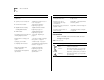
ABOUT THIS GUIDE For information on Turn to Cabling rules and pin assignments: ■ System processor serial ports “Cabling the System Processor Ports” on page 31 ■ Fast Ethernet modules “Fast Ethernet Modules” beginning on page 34 ■ ■ Gigabit Ethernet modules, including GBIC modules “Gigabit Ethernet Modules” beginning on page 37 FDDI modules “Cabling FDDI Modules” beginning on page 42 Performing system power up and checking diagnostics LEDs “Power Up” beginning on page 47 Deciding how to
CoreBuilder 3500 Documentation Table 2 Text Conventions Convention Description Syntax The word “syntax” means that you must evaluate the syntax provided and supply the appropriate values. Example: CoreBuilder 3500 Documentation The following documents comprise the documentation set. Documents are available in one of two forms: ■ CCYY-MM-DDThh:mm:ss The word “command” means that you must enter the command exactly as shown in text and then press Return or Enter.
ABOUT THIS GUIDE Paper Documents These documents are shipped with your system: ■ CoreBuilder 3500 Unpacking Instructions Each module and field-replaceable unit is shipped with a guide: ■ How to unpack your system. Also an inventory list of all the items that are shipped with your system. ■ CoreBuilder 3500 Software Installation and Release Notes Information about the software release, including new features, software corrections, and known problems.
Documentation Comments Software and Documents on CD-ROM The compact disc that comes with your system contains the system software, online versions of the paper guides that are shipped with your system, and this documentation: ■ ■ Documentation Comments Your suggestions are very important to us. They help us to make our documentation more useful to you. Please send e-mail comments about this guide to: Command Reference Guide sdtechpubs_comments@ne.3Com.
ABOUT THIS GUIDE
1 SYSTEM AND SETUP OVERVIEW This chapter contains: ■ An overview of 3Com’s CoreBuilder® 3500 Layer 3 high-function switch ■ Information on how this switch provides system solutions for your network ■ Network configuration examples ■ A description of the major features and components of the system Layer 3 High-Function Switch The CoreBuilder 3500 Layer 3 high-function switch is a modular, standalone networking device that supports high-performance Fast Ethernet, Gigabit Ethernet, and FDDI interface
CHAPTER 1: SYSTEM AND SETUP OVERVIEW The system is tuned for performance migration and bandwidth management. It supports the forwarding of switched routed packets at wire speed on all ports. The switch is designed to act as a backbone LAN router, replacing legacy LAN routers for Layer 3 forwarding functionality. It can also be used as an edge device, performing Layer 3 forwarding when you connect it to a Gigabit Ethernet backbone.
Network Configuration Examples Features of the System The CoreBuilder 3500 system combines Fast Ethernet, Gigabit Ethernet, FDDI, transparent bridging, VLAN, and intranetwork routing in a single system. These concepts are described in detail in the CoreBuilder 3500 Implementation Guide. This Layer 3 high-function switch includes integrated management to provide fault tolerance and maximum network availability.
CHAPTER 1: SYSTEM AND SETUP OVERVIEW Figure 1 CoreBuilder 3500 Used as a Workgroup Switch Subnet 1 Subnet 4 Subnet 2 Subnet 5 Subnet 3 Subnet 6
Network Configuration Examples Figure 2 CoreBuilder 3500 Used as a Gigabit Ethernet Backbone Switch SAS SAS FDDI trunking GE CoreBuilder® 3500 SuperStack® II Switch 9300 SuperStack II Switch 9300 GE GE SuperStack® II Switch 3900 SuperStack II Switch 3900 10/100 M 10/100 M 19
CHAPTER 1: SYSTEM AND SETUP OVERVIEW System Overview — Front Panel System processor serial ports For connecting a modem or terminal to the system for management access System processor LEDs For system status information System support switches For 3Com support and service personnel PCMCIA slot For software storage and upgrades System processor out-of-band port For remote and diagnostic access PCMCI MODEM INS R TERMINAL ETHERNET 10BT ERROR R N S PWR RUN 100 BASE - TX 3C35210 PWR INS ERR SYS
System Overview — Back Panel System Overview — Back Panel Power supply latch DC OK DC OK ! ! Power Supply No. 2 Power Supply No.
CHAPTER 1: SYSTEM AND SETUP OVERVIEW CoreBuilder 3500 Modules The CoreBuilder 3500 Layer 3 high-function switch has five slots. The longest slot, across the top of the device, holds the system processor. The slots below the system processor can hold up to four network-interface modules. The system processor and modules are described in the following sections. System Processor Module The system processor stores, boots, and executes the system software.
CoreBuilder 3500 Modules Fast Ethernet Modules Each system can accommodate up to four Fast Ethernet modules. The modules are hot-swappable. The Fast Ethernet modules are available in these configurations: ■ ■ 23 Module specifications for the Fast Ethernet modules are provided in Table 3 and Table 4.
CHAPTER 1: SYSTEM AND SETUP OVERVIEW FDDI Modules FDDI modules are available in the following configurations: ■ ■ FDDI MMF — Connects to multimode fiber-optic cable and provides a transmission distance of up to 2 km (1.24 mi) using 62.5-micron fiber. FDDI SMF — Connects to single-mode fiber-optic cable and provides a transmission distance of up to 14.4 km (8.95 mi) using 9-micron fiber.
CoreBuilder 3500 Modules Gigabit Ethernet Modules Gigabit Ethernet modules are supported in the following configurations: ■ 1000BASE-SX The single-port Gigabit Ethernet module supports 1000BASE-SX MMF in either 62.5-micron or 50-micron multimode fiber. ■ 1000BASE GBIC The single-port GBIC (Gigabit Interface Converter) module uses a 1000BASE GBIC transceiver to connect to your Gigabit Ethernet network. Each system can accommodate up to four Gigabit Ethernet modules. The modules are hot-swappable.
CHAPTER 1: SYSTEM AND SETUP OVERVIEW
INSTALLING THE SYSTEM 2 This chapter describes how to install your CoreBuilder® 3500 system on a table top or in a distribution rack.
CHAPTER 2: INSTALLING THE SYSTEM Installing the System in a Distribution Rack 2 Carefully lift the system into place, aligning the You can mount the system into a standard 19-inch distribution rack. This section describes how to prepare the system and rack and how to mount the system. For information on distribution rack requirements, see Appendix C.
3 INSTALLING MEDIA MODULES Your CoreBuilder® 3500 system is shipped with the system processor installed but with no modules installed. Protective blank faceplates cover the module installation slots. To prepare the system for configuration, read these sections: ■ Avoiding ESD Damage ■ Installing a Module For specific module overview, LED status information, installation instructions, and diagnostics information, see the module installation guide that is shipped with each module.
CHAPTER 3: INSTALLING MEDIA MODULES Figure 10 shows a module that is being installed in a system. 5 Remove the faceplate by grasping the injector/ejector handles and simultaneously rolling them outward. See Figure 9. Save the faceplate for future use.
4 CABLING This chapter describes how to cable your CoreBuilder® 3500 system for connecting these elements to your network: ■ System processor ports ■ Fast Ethernet modules ■ Gigabit Ethernet modules ■ FDDI modules When all your Fast Ethernet, Gigabit Ethernet, FDDI, and system network connections are complete, see Chapter 5. If you are staging the system, you do not need to connect it to the network yet.
CHAPTER 4: CABLING Figure 11 Cabling the System Processor Serial Ports Modem port INS Terminal port MODEM TERMINAL Figure 12 Cabling the Out-of-band Port Out-of-band Ethernet port ETHERNET 10BT INS MODEM TERMINAL ETHERNET 10BT VIC VICE 100 BASE - TX 1X 3C35210 L E T PWR INS ERR 3X 4X 2X L E T L E T L E T 5X 6X L E T L E T DB-9 Connectors You are now ready to configure your system for management access through the serial ports. See Chapter 6.
Cabling the System Processor Ports Processor Port Pin Assignments Table 7 Terminal Port Pin Assignments This section describes the pin assignments for the management access ports on the system processor. Pin No. Table 6 shows the modem port pin assignments. 2 RXDB Received data Table 7 shows the terminal port pin assignments. 3 TXDB Transmitted data Table 8 shows the pin assignments for the out-of-band 10BASE-T Ethernet port.
CHAPTER 4: CABLING Fast Ethernet Modules Figure 13 Cabling the 10/100BASE-TX Module Your network’s Fast Ethernet segments connect to the CoreBuilder 3500 system through Fast Ethernet modules, which come in two versions: ■ 10/100 BASE-TX with six twisted-pair RJ-45 connectors, discussed next ■ 100BASE-FX with six fiber SC connectors, discussed in the “Cabling the 100BASE-FX Module” section beginning on page 36 R ER R N S PWR RUN 100 BASE - TX 3C35210 INS PS1 1X L E T 2X L E T 3X L E T 4X
Fast Ethernet Modules 10/100BASE-TX Port Pin Assignments Table 9 shows the port pin assignments for the 10/100BASE-TX port. Table 9 10/100BASE-TX Port Pin Assignments Pin No. Signal Description 1 RD + Receive Data + 2 RD – Receive Data – 3 TD + Transmit Data + 4 Not used 5 6 Not used TD – 35 Fiber and Laser Safety Precautions The 100BASE-FX Fast Ethernet modules, Gigabit Ethernet modules, and FDDI modules use light-emitting diodes (LEDs) and lasers in their fiber-optic ports.
CHAPTER 4: CABLING Cabling the 100BASE-FX Module The 100BASE-FX module has six Fast Ethernet ports that use SC connectors and provide 100 Mbps Fast Ethernet connections over fiber cabling. The 100BASE-FX module is available for either single-mode fiber (SMF) or multimode fiber (MMF).
Gigabit Ethernet Modules Gigabit Ethernet Modules Your Gigabit Ethernet network connects to the system through a Gigabit Ethernet module. This single-port module is supported in these configurations: ■ ■ 1000BASE-SX MMF Module — Can be used with either 62.5-micron or 50-micron multimode fiber. See “Cabling the 1000BASE-SX MMF Module” next for details. 1000BASE GBIC Module — Connects to your Gigabit Ethernet network using a 1000BASE-LX or 1000BASE-SX Gigabit Interface Converter (GBIC) transceiver.
CHAPTER 4: CABLING ■ Use 9-micron SMF fiber for distances of up to 10 kilometers (6.2 miles). The specification requires and specifies 5 kilometers (3.1 miles). Figure 15 Cabling the 1000BASE-SX Module Use a conditioned launch cable to connect the 1000BASE-LX transceiver to multimode fiber. Using this cable ensures reliability over the maximum 550 m distance.
Gigabit Ethernet Modules Cabling the 1000BASE GBIC Module The 1000BASE GBIC module provides one GBIC (Gigabit Interface Converter) port that accepts one of these transceivers: ■ ■ 1000BASE-LX GBIC — Use this transceiver to connect the GBIC module directly to a single-mode fiber-optic cable or to multimode fiber using a conditioned launch cable. For instructions on using this transceiver to connect to single-mode fiber, follow the procedure in this section.
CHAPTER 4: CABLING 3 If you have not already done so, remove the SC Figure 18 Cabling the GBIC Module connector cover from the transceiver, as shown in Figure 17. Figure 17 Removing the SC Connector Cover MODEM INS TERMINAL ETHERNET 10BT C 1000 BASE (GBIC) 3C35330 SC connector cover PWR INS ERR L E T 4 Attach the male duplex SC connector on the network cable into the duplex SC port on the GBIC transceiver, as shown in Figure 18.
Gigabit Ethernet Modules Connecting the LX Transceiver to MMF The LX transceiver supports a connection to multimode fiber by means of a conditioned launch cable. The conditioned launch cable consists of an offset mechanism on the transmit side of the cable that aligns the single-mode laser launch away from the center of the multimode fiber core, creating a transmission signal similar to launches from typical multimode light-emitting diodes (LEDs).
CHAPTER 4: CABLING Figure 19 Connecting Using a Conditioned Launch Cable Cabling FDDI Modules Your network’s FDDI segments connect to the CoreBuilder 3500 system through FDDI modules, which come in two versions: MODEM INS TERMINAL ■ FDDI MMF — Connects to multimode fiber-optic cable ■ FDDI SMF — Connects to single-mode fiber-optic cable ETHERNET 10BT C 1000BASE GBIC module Both modules contain six FDDI ports that use duplex SC fiber-optic connectors.
Cabling FDDI Modules When module availability and connectivity is crucial, you can connect your DAS-configured module to the network using dual homing. For more information, see the FDDI chapter in the CoreBuilder 3500 Implementation Guide. For more information on configuring DAS and SAS modes, see the fddi stationMode modify command in the Command Reference Guide.
CHAPTER 4: CABLING Figure 20 Cabling the SAS Connection SAS port MODEM INS TERMINAL ETHERNET 10BT Cabling a Dual-Attached Station An FDDI module connected as a dual-attached station (DAS) is connected to both the primary and secondary rings of an FDDI network. Use DAS connections where reliability is important and additional fault tolerance is required. Each DAS connection consists of an A port and a B port.
Cabling FDDI Modules For more information about dual-attached stations, see the CoreBuilder 3500 Implementation Guide. 45 Figure 22 Cabling the DAS Connection DAS port A To cable the module as a dual-attached station: 1 Read and follow the “Fiber and Laser Safety DAS port B Precautions” on page 35 for safe operation. 2 Configure a DAS connection on your FDDI module. This connection involves configuring the ports that you are working with to support DAS mode.
CHAPTER 4: CABLING
SYSTEM POWER UP 5 This chapter contains: ■ Instructions for powering up the CoreBuilder® 3500 system ■ Description of power-up diagnostics ■ Items to check after system power up CAUTION: To prevent a possible fire hazard, ensure that the power cord is fully inserted. Figure 23 System Power Receptacle Power supply latch If you have any problems in powering up your system, see Chapter 7. Power Up DC OK To get your system powered up and ready to operate, follow the steps in this section.
CHAPTER 5: SYSTEM POWER UP Power-up Diagnostics The system automatically runs diagnostic software at power up. This software verifies that every component in the system is operating correctly. If any component fails during power-up diagnostics, the system either fails to power up or the faulty module comes up but all of its ports are out of service.
System Processor LEDs System Processor LEDs Figure 24 System Processor LEDs RUN Blinking Green System is operating correctly Steady Green System is running diagnostics PWR (Power) Green System is powered on PCMCIA INS MODEM TERMINAL ERROR R N S PWR RUN SYS INS PS1 PS2 FAN TEMP SERVICE INS (Inserted) Green PCMCIA card inserted in system SYS (System Processor) Steady Yellow SERVICE Yellow System processor has failed at power up System service mode is active Blinking Yellow Hardware/softwa
CHAPTER 5: SYSTEM POWER UP System Diagnostics — LED Activity When you first power up the system, the system processor PWR LED and RUN LED light green, indicating that the system is receiving power and running diagnostics. After the system diagnostics are successfully completed, the RUN LED blinks green, indicating that the system is operating. If the SYS LED lights yellow, the system processor has failed at power up. If the system processor fails, see Chapter 7 for troubleshooting information.
System Checks Table 11 summarizes the module LED activity. System Checks After the system has successfully completed the power-up diagnostics, check the items in Table 12 to verify that the system is operating correctly. Table 11 Module Diagnostics — LED Activity LED Name Color Indicates ERR (Error - Module) Steady yellow Diagnostics failed. Blinking yellow A hardware/software mismatch has occurred. . E (Error - Port) Yellow Port not operational.
CHAPTER 5: SYSTEM POWER UP Next Step: Software Configuration Your system is shipped from the factory with IEEE 802.1 bridging set to disabled. To configure your system for your particular networking environment (including SNMP set up, customized packet filtering, and routing), you must first establish management access. See the procedures in Chapter 6.
6 QUICK SETUP FOR MANAGEMENT ACCESS This chapter provides easy instructions for configuring the CoreBuilder® 3500 system for management access. After you decide how you want to manage your system, follow the configuration instructions for your preferred type of management access. About System Management The Administration Console is an internal, character-oriented, menu-driven user interface for performing system administration.
CHAPTER 6: QUICK SETUP FOR MANAGEMENT A CCESS Terminal Port Direct access through the system processor terminal port allows you to remain on the system and monitor it during system boots. A Macintosh or PC attachment can use any terminal emulation program for connecting to the terminal serial port. A workstation attachment under UNIX can use the emulator TIP.
Modem Setup Setting the Terminal Port Baud Parameter To change the baud setting of the terminal port from the Administration Console, follow these steps: 1 From the top level of the Administration Console, enter: 55 Modem Setup You can set up your system for access through an external modem that is attached to the system processor’s modem port. To do this, you must first set the baud setting of the modem port (if necessary), and then attach and configure your external modem.
CHAPTER 6: QUICK SETUP FOR MANAGEMENT A CCESS Connecting to an External Modem To connect to and configure the external modem port, follow these steps: 1 From the top level of the Administration Console, Configuring the IP Management Interface These instructions include information on defining an out-of-band IP management interface through which you can manage your system.
Configuring the IP Management Interface Out-of-band Management To manage your system out-of-band, you need to assign an IP address and subnet mask to the out-of-band Ethernet port on your system. The out-of-band Ethernet port is labeled “Ethernet 10BT” on the system processor module. An out-of-band IP management interface contains the following parameters: ■ ■ IP address — Use this address, which is specific to your network, for managing the system.
CHAPTER 6: QUICK SETUP FOR MANAGEMENT A CCESS
7 TROUBLESHOOTING THE SYSTEM This chapter explains how to troubleshoot certain problems within the CoreBuilder® 3500 system. It covers how to identify and correct system problems and suggests some steps that you can take if you cannot resolve the problem. Getting Additional Help If you experience system problems that are not addressed in this chapter, contact 3Com Technical Support or your service representative.
CHAPTER 7: TROUBLESHOOTING THE SYSTEM Diagnosing Problems By observing system diagnostics and reviewing the tables in this chapter, you can identify and correct problems that can occur at system power up. Power Failures If the system does not respond when you insert the power cord, see the troubleshooting suggestions in Table 14. Abnormal LED Activity The system processor contains several status LEDs that indicate system problems.
Diagnosing Problems Table 14 Troubleshooting Power Failures Symptom Possible Sources of the Problem System does not power up. ■ System is not receiving power. Steps to Take 1 Verify that the building’s power outlet has power. ■ Power supply has malfunctioned. 2 Verify that the power cord is firmly inserted into the system and into the building’s power outlet. 3 If the system still does not operate, contact your network supplier or 3Com Technical Support.
CHAPTER 7: TROUBLESHOOTING THE SYSTEM Table 15 Troubleshooting Abnormal Status Activity on the System Processor LEDs LED Status Possible Sources of the Problem Steps to Take RUN LED does not light. Diagnostic software is not running. Contact your network supplier or 3Com Technical Support. SYS LED lights yellow. System processor has failed. 1 Disconnect the power cord. SYS LED blinks yellow. Hardware/software mismatch 2 Contact your network supplier or 3Com Technical Support.
Diagnosing Problems Table 16 Troubleshooting Abnormal Activity on the Module Status LEDs LED Status Possible Sources of the Problem Steps to Take PWR LED lights yellow. Module has failed. Replace the module with a new one. INS LED lights yellow. Module is not completely inserted. Reseat the module. ERR LED lights steady yellow. Module has failed. Replace the module with a new one. ERR LED blinks yellow. Hardware/software incompatibility 1 If you have added a new module, remove it.
CHAPTER 7: TROUBLESHOOTING THE SYSTEM
A SYSTEM SPECIFICATIONS Physical Dimensions 13.2 cm H x 44.0 cm W x 42.42 cm D* (5.2 in. H x 17.3 in. W x 16.7 in. D*) *Depth includes protrusion of power supply handles — 3.12 cm (1.23 in.) Weight (fully loaded with 2 power supplies): 18.14 kg (40.01 lb) Environmental Requirements Operating temperature 0 to 50 °C (32 to 122 °F)* *Maximum operating temperature is at sea level. It increases 1.8 °C for every 1000 m above sea level (1 °F for every 3280 ft above sea level).
APPENDIX A: SYSTEM SPECIFICATIONS Electromagnetic Emissions (Agency Certification) FCC part 15, Subpart B, Class A limits EN 55 022 (CISPR-22) (Europe) VCCI (Japan) CE Mark Immunity EN50082-1 (IEC 801 Series) Heat Dissipation 362 watts maximum (1237 BTU/hour maximum) Power Supply AC line frequency 47 to 63 Hz Input voltage options 90 VAC to 264 VAC Current rating 100 VAC at 3.8 amperes (maximum) or 240 VAC at 1.
Standards Supported SNMP Software Installation ■ BRIDGE-MIB.mib — Bridge MIB, RFC 1493 ■ FTP (RFC 959) ■ ETHERNET.mib — Ethernet MIB, RFC 1398 ■ TFTP (RFC 1350) ■ FDDI-SMT73-MIB.mib — FDDI SMT 7.3 MIB, RFC 1512 ■ FDDI-MIB.mib — FDDI Station Management MIB, RFC 1285 Terminal Emulation Protocols ■ IANAifType-MIB-V1SMI.mib — Internet Assigned Numbers Authority MIB, SMI Version 1, RFC 1573 ■ Telnet (RFC 854) ■ rlogin (RFC 1282) ■ IF-MIB-V1SMI.
APPENDIX A: SYSTEM SPECIFICATIONS Standards Supported (cont.) 3Com Enterprise MIBs allow you to manage unique and advanced functionality of 3Com devices. ■ 3cFddi.mib — 3Com FDDI MIB (43.29.10) ■ 3cFilter.mib — 3Com Packet Filtering MIB, standard and custom (43.29.4.20) ■ 3cPolicy.mib — 3Com Policy Management MIB (43.29.4.23) ■ 3cPoll.mib — 3Com Remote Polling MIB (43.29.4.22) ■ 3cProd.mib — 3Com Transcend Product Management MIB (43.1) ■ 3cQos.mib — 3Com QoS MIB (43.29.4.21) ■ 3cSys.
System LEDs System Status LEDs ■ PWR (Green): System is powered on. ■ RUN (Green): System is running diagnostics. ■ RUN (Blinking Green): System is operating correctly. ■ SYS (Yellow): Processor failed at power up. ■ SYS (Blinking Yellow): Hardware/software revision mismatch. ■ INS (Yellow): Processor is not fully inserted. ■ PS1 and PS2 (Yellow): Power supply is not inserted, is out of specification, or has failed. ■ FAN (Yellow): Fan has slowed or shut down.
APPENDIX A: SYSTEM SPECIFICATIONS
FIELD-REPLACEABLE COMPONENTS B This appendix contains information on how to remove and replace the CoreBuilder® 3500 field-replaceable components. The components include: ■ System processor ■ Modules ■ Power supply assembly ■ Fan tray assembly Also included is information on replacing the system battery and upgrading the system memory. Only trained technical personnel may remove and install the system processor, modules, power supply, system memory, and system battery.
APPENDIX B: FIELD-REPLACEABLE COMPONENTS ESD Safety Information Electrostatic discharge (ESD) can damage components on the system processor board or on a module. ESD, which occurs when the board is improperly handled, can cause intermittent failures. To prevent ESD-related damage: ■ ■ Always wear an ESD wrist strap, ensuring that it makes good skin contact and is attached to a proper ground. Keep the board in its antistatic shielded bag until you are ready to install it.
Module Removal and Replacement Figure 25 Removing and Replacing the System Processor System processor Captive screw 73 Module Removal and Replacement You can remove and replace a module with the power on. To remove and replace a module, follow the steps in this section.
APPENDIX B: FIELD-REPLACEABLE COMPONENTS CAUTION: If the resistance is too great, the module connectors and backplane connectors may not be aligned. Forcing the module forward can damage the board and backplane connectors. If necessary, remove and reinsert the module, ensuring that the connectors are properly aligned. Do not seat the module by tightening the captive screws.
Fan Tray Assembly Removal and Replacement 7 Tighten the captive screws that secure the power supply to the chassis. 8 Lift the power supply latch and insert the power cord into the system. 9 Insert the other end of the power cord into the building’s power outlet. If your system has two power supplies, be sure to connect the second power supply. Leaving the second power supply installed but not connected to the power outlet causes the system diagnostics to generate a power supply error.
APPENDIX B: FIELD-REPLACEABLE COMPONENTS Figure 28 Removing and Replacing the Fan Tray R PWR RUN R N S SYS INS 100 BASE - TX 1X 3X 4X 2X 3C35210 L E T L E T L E T L E T PWR INS ERR 100 BASE - TX 1X 3X 4X 2X 3C35210 L E T L E T L E T L E T PWR INS ERR ACHTUNG: Explosionsgefahr, Falls die Batterie falsch eingesetzt ist. Benutzt die Batterie order equivalent type (Gleichwertige), die vom Hersteller empfohlen wird (Tadiran Model TL-5111). Die Batterie wird nach dem Herstellersvorschriften beseitigt.
System Processor Battery Replacement Figure 29 Removing the System Battery Installing the Battery To install the new battery onto the system processor, follow the steps in this section. Top of battery case Battery R 3. 6 2 Place the new battery into the battery case, verifying that the polarity (+/–) on the battery matches the polarity that is marked on the system processor.
APPENDIX B: FIELD-REPLACEABLE COMPONENTS
C SITE REQUIREMENTS AND SAFETY CODES This appendix summarizes the criteria that your site must meet for the CoreBuilder® 3500 system to operate safely and effectively.
APPENDIX C: SITE REQUIREMENTS AND SAFETY CODES ■ Be sure that each wiring closet has a suitable ground. Ground all metal racks, enclosures, boxes, and raceways in the closet. ■ Use AC power, 15-amp service receptacles, type N5/15 or NEMA 5-15R for 120VAC, and the other system specifications shown in Appendix A. ■ Be especially sure to meet all system environmental requirements in Appendix A, such as ambient temperature and humidity.
Distribution Rack Requirements Figure 30 Recommended Service Access 81 Mechanical Requirements for the Rack Verify that your racks comply with the standards and requirements as specified in your cabling system plan and also that they conform to certain conventional standards: ■ In the United States, use EIA Standard RS-310C: Racks, Panels, and Associated Equipment. ■ In countries other than the United States, use IEC Standard 297: Dimensions of Panels and Racks.
APPENDIX C: SITE REQUIREMENTS AND SAFETY CODES Figure 31 Recommended Rack Styles Building and Electrical Codes Follow all appropriate building codes and authorities on electrical codes when planning your site and installing your cable for the system. Specific building and electrical codes vary depending on your location. The following lists are provided as resources to help you find additional information.
Building and Electrical Codes U.S. Electrical Codes ■ Authorities on electrical codes: ■ National Electrical Code (NEC) Classification — A recognized authority on safe electrical wiring. U.S. Federal, state, and local governments use NEC standards to establish their own laws, ordinances, and codes on wiring specifications. The NEC Classification is published by: National Fire Protection Association (NFPA) 1 Batterymarch Park P.O. Box 9101 Quincy MA 02269-9109 USA www.nfpa.
APPENDIX C: SITE REQUIREMENTS AND SAFETY C ODES
D TECHNICAL SUPPORT 3Com provides easy access to technical support information through a variety of services. This appendix describes these services. Information contained in this appendix is correct at time of publication. For the most recent information, 3Com recommends that you access the 3Com Corporation World Wide Web site.
APPENDIX D: TECHNICAL SUPPORT 3Com FTP Site Download drivers, patches, software, and MIBs across the Internet from the 3Com public FTP site. This service is available 24 hours a day, 7 days a week. To connect to the 3Com FTP site, enter the following information into your FTP client: Country Data Rate Telephone Number Hong Kong Up to 14,400 bps 852 2537 5601 Italy Up to 14,400 bps 39 2 27300680 Japan Up to 14,400 bps 81 3 5977 7977 Mexico Up to 28,800 bps 52 5 520 7835 P.R.
Support from Your Network Supplier Support from Your Network Supplier 87 Support from 3Com If you require additional assistance, contact your network supplier. Many suppliers are authorized 3Com service partners who are qualified to provide a variety of services, including network planning, installation, hardware maintenance, application training, and support services.
APPENDIX D: TECHNICAL SUPPORT Here is a list of worldwide technical telephone support numbers: Country Asia Pacific Rim Australia Hong Kong India Indonesia Japan Malaysia New Zealand Pakistan Philippines P.R. of China Singapore S. Korea From anywhere in S. Korea: From Seoul: Taiwan, R.O.C.
Returning Products for Repair Returning Products for Repair Before you send a product directly to 3Com for repair, you must first obtain an authorization number. Products sent to 3Com without authorization numbers will be returned to the sender unopened, at the sender’s expense.
APPENDIX D: TECHNICAL SUPPORT
INDEX Numbers 3Com bulletin board service (3Com BBS) 86 3Com Facts 86 3Com training 71 3Com URL 85 A Administration Console configuring IP addresses 56 configuring modem port 55 configuring terminal port 55 air conditioning 80 antistatic bag 29 B baud setting 55 building codes BOCA (Basic Building Code) 82 ICBO (International Conference of Building Officials) 82 SBC (Standard Building Code) 82 Uniform Building Code 82 bulletin board service 86 C cable 31 cabling 10/100BASE-TX modules 34 1000BASE-LX tran
INDEX G M P GBIC modules cabling 39 cabling to MMF using LX transceiver 41 conditioned launch cables 41 Gigabit Interface Converters (GBICs) 39 to 41 Gigabit Ethernet module described 25 management access ports on the system processor 31 management, system IP 53 modem 53 terminal 53 MIBs 67 modem port and system management 53 cabling 31 configuring 55 connecting to external 55 pin assignments 33 quick configuration 55 setting the baud rate 55 modules diagnostics 50 grounding during installation 29,
INDEX S safety connecting to proper ground 29, 77 fiber precautions 35 requirements 79 SAS (single-attached station) cabling 43 SBC (Standard Building Code) 82 SC connectors 37 serial line and management access 53 serial port modem 53 pin assignments 33 terminal 53 SERVICE LED 49 single-attached station (SAS) cabling 43 site planning environmental and safety requirements 79 rack requirements 80 wiring closet considerations 79 SNMP 53 software release notes 9 standards supported 67 subnet mask 57 SX transce
INDEX
3Com Corporation LIMITED WARRANTY CoreBuilder® 3500 High-Function Switch HARDWARE YEAR 2000 WARRANTY 3Com warrants to the end user (“Customer”) that this hardware product will be free from defects in workmanship and materials, under normal use and service, for one (1) year from the date of purchase from 3Com or its authorized reseller.
Dead- or Defective-on-Arrival. In the event a product completely fails to function or exhibits a defect in materials or workmanship within the first forty-eight (48) hours of installation but no later than thirty (30) days after the date of purchase, and this is verified by 3Com, it will be considered dead- or defective-on-arrival (DOA) and a replacement shall be provided by advance replacement.