
Manual


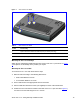
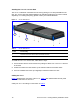
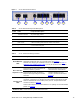
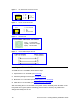
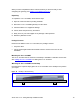
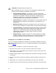

Figure 6 RJ-45 Ethernet Connector Pinouts
1 2 3 4 5 6 7 8
RJ-45 Connector and Pinout
4, 5, 7, 8
not
connected
1 - Tx+
2 - Tx-
3 - Rx+
6 - Rx-
Figure 7 Phone Connector Pinouts
1 2 3 4
1 -
2 -
3 -
4 -
Not connected
RJ-11 Connector and Pinout
Not connected
Tip
Ring
Figure 8 PS/2 Pinouts
2
3
6
PS/2 Female Connector and Pinout
(TD) - Transmit Data
(RD) - Receive Data
(GND) - Ground for Voltage
Figure 9 PS/2 to DB-9 Adaptor Pinouts
Installing the V7111 24-PORT
To install the V7111 24-PORT, follow these 4 steps:
1 Unpack the V7111 24-PORT (see
Unpacking).
2 Check the package contents (see
Package Contents).
3 Mount the V7111 24-PORT (see
Mounting the V7111 24-PORT).
4 Cable the V7111 24-PORT (see
Cabling the V7111 24-PORT).
After connecting the V7111 24-PORT to the power source, the Ready and LAN LEDs on the
front panel turn to green (after a self-testing period of about 1 minute). Any malfunction
changes the Ready LED to red.
18 3Com VCX V7111 Analog Gateway Installation Guide