3Com® AirProtect Enterprise Engine 6100 Quick Setup Guide www.3Com.com Part Number: 10015863 Rev.
3Com Corporation 350 Campus Drive, Marlborough, MA USA 01752-3064 Copyright © 2003 – 2007 3Com Corporation and its Licensors. All Rights Reserved. 3Com Corporation reserves the right to revise this documentation and to make changes in content from time to time without obligation on the part of 3Com Corporation to provide notification of such revision or change.
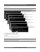
Step 1: 3Com AirProtect Enterprise Appliance and 3Com AirProtect Sensor Overview The front panel of the appliance has a power switch and status LEDs as shown in the figure below. The rear panel of the appliance has power and port connectors as shown in the figure below. The front panel of 3Com AirProtect Sensor has status LEDs as shown in the figure below.
Step 2: Mount the Appliance Place the appliance on the rack and mount the appliance using the rack mounting accessories.
Step 3: Power up the Appliance Connect the power cable as shown in the figure below and press the power switch on the front panel of the appliance. 110-240V 50/60 Hz AC Connection Important! On connecting the Power cable, the Power LED should turn solid green. If this does not happen, refer to the 3Com AirProtect Enterprise Installation Guide. Step 4: Connect the Appliance to the Network Connect the appliance to the network using the network interface cable as shown in the figure below.
Step 5: Access 3Com AirProtect Enterprise A. Connect your computer to the same subnet where the Server is connected. B. Change your computer IP address to 192.168.1.XXX. For example, 192.168.1.244. C. Access 3Com AirProtect Enterprise using SSH as shown in the figure below. D. Login using the Username: config and Password: password.
Step 6: Complete the Server Initialization and Setup Wizard Follow the steps in the Server Initialization and Setup Wizard to configure the 3Com AirProtect Enterprise Server. Important! On the Date and Time settings screen‐Step 3, if the day exceeds 31 and the month exceeds 12, 3Com AirProtect Enterprise automatically sets the day to 31 and month to 12.
Step 7: Set up the Server DNS Entry Add a DNS entry ‘wifi‐security‐server’ in your organization’s/enterprise DNS server. This entry should point to the IP Address of the Server configured in Step 6 (Complete Server Initialization and Setup Wizard)—Sub step 2 (Change the Network Settings). Adding this entry serves two purposes: A. Sensors can connect to the Server with “zero configuration” if they are connected to a DHCP enabled subnet. B.
C. Type the default username: admin and password: password on the Login screen. Login Information Important! If you see a blank screen instead of the 3Com AirProtect Enterprise Console Login screen in the pop‐up window, despite having Sun JRE 1.4.2, then Sun JRE 1.4.2 may not be the default plug‐in for your Web browser. To ensure that Sun JRE 1.4.2 is the default plug‐in for your Web browser, do the following: 1.
E. If you see the Welcome screen, close the window. You are done with the Server Setup. You will revisit the Welcome screen later.
Step 9: Connect 3Com AirProtect Sensors to the Network Power and Connect to the Network A. Ensure that the 3Com AirProtect Enterprise Server is already running on your network. Note: Make sure that a DNS entry ‘wifi‐security‐server’ is set up on all DNS Servers. This entry should point to the IP address of the Server. Otherwise, configure the Sensor manually. Please refer to the 3Com AirProtect Enterprise Installation Guide for details. B.
Important! If the LED status at the end of Step D does not match the status shown in this Quick Setup Guide, refer to the 3Com AirProtect Enterprise Installation Guide for more details. Step 10: Begin the System Setup Wizard and Select Installation Type A. Log in to the 3Com AirProtect Enterprise Console with the default username: admin and password: password. B.
Step 11: Complete the 3Com AirProtect Enterprise System Setup Wizard Follow the steps in the System Setup Wizard to specify the 802.11 Security, Device Classification, and Intrusion Prevention Policies. Click the icon to view details.
Step 12: Enable Global Flags Event generation and intrusion prevention activation flags are turned off globally on completion of the System Setup Wizard to avoid spurious generation of events. The Activation of Intrusion appears on the Navigation bar as shown in the figure Prevention and Event Generation icon below.