EtherLink® XL PCI 10 Mbps Network Interface Cards User Guide Member of the 3Com EtherLink XL family of network interface cards http://www.3com.com/ Part No.
3Com Corporation ■ 5400 Bayfront Plaza ■ Santa Clara, California ■ 95052-8145 Copyright © 1998, 3Com Corporation. All rights reserved. No part of this documentation may be reproduced in any form or by any means or used to make any derivative work (such as translation, transformation, or adaptation) without written permission from 3Com Corporation.
CONTENTS ABOUT THIS GUIDE Finding Specific Information in This Guide Conventions 2 1 1 INSTALLING THE NETWORK INTERFACE CARD Preparing for Installation 1-2 Inserting the NIC 1-3 Connecting to the Network 1-5 RJ-45 Port 1-5 BNC Port 1-6 AUI Port 1-7 Interpreting the Link LED 1-8 2 INSTALLING THE NETWORK DRIVER Windows 95 2-1 Windows 95 Build 950 2-2 Windows 95 OSR2 2-4 Confirming Installation 2-6 Windows NT 2-6 Windows NT 4.0 2-7 Windows NT 3.
3Com DOS Diagnostic Program 3-2 3Com NIC Diagnostics Program 3-2 Running NIC Tests 3-2 Running the Echo Test 3-4 3Com Support Services 3-7 Accessing the Help System 3-8 Release Notes, Frequently Asked Questions, and KnowledgeBase Topics 3-8 Removing NIC Software 3-9 Windows 95 and Windows NT 4.0 3-9 Windows NT 3.
Changing Ranges and Protocols B-4 C TROUBLESHOOTING NETWORK CONNECTION PROBLEMS Eliminating Potential Causes of Problems C-1 Troubleshooting Hubs with Crossover Cable C-2 D TECHNICAL SUPPORT Support from Your Network Supplier D-1 Online Technical Services D-1 World Wide Web Site D-2 3Com Bulletin Board Service D-2 Access by Analog Modem D-2 Access by Digital Modem D-3 3ComFacts Automated Fax Service D-3 INDEX 3COM CORPORATION LIMITED WARRANTY FCC CLASS B STATEMENT FCC DECLARATION OF CONFORMITY 3COM END
FIGURES 1-1 1-2 1-3 1-4 1-5 2-1 3-1 3-2 3-3 3-4 3-5 3-6 4-1 4-2 4-3 4-4 A-1 B-1 C-1 3C900B Network Interface Cards 1-1 Installing the 3C900B NIC 1-4 Connecting to the RJ-45 Port on the 3C900B NIC 1-5 Connecting to the BNC Port on the 3C900B-COMBO NIC Connecting to the AUI Port on the 3C900B-COMBO NIC Selected NIC Screen of the Configuration and Diagnostic Program 2-13 3Com NIC Diagnostics General Screen 3-3 Diagnostics Screen 3-4 Echo Test Responder Screen 3-5 Echo Test Sender Screen 3-6 Echo Test Statist
TABLES 1 2 1-1 1-2 2-1 3-1 4-1 A-1 viii Notice Icons 2 Text Conventions 2 3C900B NIC Models 1-2 LED Interpretation 1-8 Network Driver Text File Names 2-14 Frequently Asked Questions 3-10 Option Settings 4-1 Unshielded Twisted-pair Cable Categories A-2
ABOUT THIS GUIDE About This Guide provides an overview of this guide, describes guide conventions, and tells you where to look for specific information. This guide describes how to install, configure, and troubleshoot 3Com® EtherLink® XL PCI 10 Mbps (3C900B) network interface cards (NICs). If a release note is shipped with this product, and the information in the release note differs from the information in this guide, follow the instructions in the release note.
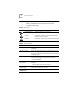
2 ABOUT THIS GUIDE Conventions Table 1 and Table 2 list conventions that are used throughout this guide. Table 1 Notice Icons Icon Notice Type Description Information note Important features or instructions Caution Information to alert you to potential damage to a program, system, or device Warning Information to alert you to potential personal injury Table 2 Text Conventions Convention Description Screen displays This typeface represents information as it appears on the screen.
1 INSTALLING THE NETWORK INTERFACE CARD This chapter describes the 3Com® EtherLink® XL PCI 10 Mbps 3C900B network interface cards (NICs). Procedures are provided for installing the NIC hardware and software and connecting each version of the NIC to an Ethernet network. Figure 1-1 shows the two versions of the 3C900B NIC. These NICs connect your PC to a 10 Mbps Ethernet network using up to three different types of media.
1-2 CHAPTER 1: INSTALLING THE NETWORK INTERFACE CARD Table 1-1 3C900B NIC Models Maximum Network Connector Transceiver Segment NIC Model Cable 3C900B-TPO Category 3, 4, or 5 unshielded twisted-pair (10BASE-T) RJ-45 On-board 328 ft/100 m 3C900B-COMBO Category 3, 4, or 5 unshielded twisted-pair (10BASE-T) RJ-45 On-board 328 ft/100 m 10BASE5 thick 15-pin AUI Ethernet coaxial External 1640 ft/500 m 10BASE2 thin BNC Ethernet coaxial On-board 1000 ft/305 m Preparing for Installation Before yo
Inserting the NIC 1-3 Inserting the NIC The following instructions apply to installing the 3C900B NIC in most PCs. If these instructions are not appropriate for your PC, refer to the documentation that accompanied your PC. CAUTION: Each NIC is packed in antistatic packaging to protect it during shipment. Before handling the NIC, touch the bare metal case of your PC. While you are handling the NIC, wear a wrist strap grounded to the PC chassis.
1-4 CHAPTER 1: INSTALLING THE NETWORK INTERFACE CARD Backplate screw 3C900B NIC PCI slot Figure 1-2 Installing the 3C900B NIC 4 Remove and discard the backplate. 5 Ensure that the shape and length of the edge connector on the NIC match the slot that you intend to use (Figure 1-2). 6 Carefully insert the NIC into the slot. Press firmly with steady pressure to ensure that the NIC is fully seated in the slot. When the NIC is correctly inserted in the slot, the NIC backplate is flush with the PC backplane.
Connecting to the Network 1-5 Connecting to the Network This section describes how to connect the 3C900B NIC to an Ethernet network using an RJ-45, BNC, or AUI port. Each 3C900B NIC provides different network ports, as shown in Figure 1-1. Follow the procedure for the network port on the NIC that you install. When you first install the NIC and power on the PC, the LED on the NIC backplate lights, but the link is not active. To enable the link, you must load the network drivers.
1-6 CHAPTER 1: INSTALLING THE NETWORK INTERFACE CARD BNC Port Follow these steps to connect the BNC port on the COMBO NIC to the network: 1 Connect the BNC connector on the thin Ethernet coaxial cable to the BNC port on the NIC. See Figure 1-4. BNC connector BNC port Figure 1-4 Connecting to the BNC Port on the 3C900B-COMBO NIC 2 Connect the other end of the network cable to another PC or a 50-ohm terminator.
Connecting to the Network 1-7 AUI Port Follow these steps to connect the AUI port (Figure 1-5) on the 3C900B COMBO NIC to the network: 1 Locate the 15-pin AUI port on the NIC and move the slide latch down to the open position. AUI port AUI connector Figure 1-5 Connecting to the AUI Port on the 3C900B-COMBO NIC 2 Connect the thick Ethernet coaxial cable to the AUI port on the NIC. This connector attaches in only one way. Orient the AUI connector to match the AUI port on the NIC.
1-8 CHAPTER 1: INSTALLING THE NETWORK INTERFACE CARD Interpreting the Link LED The 3C900B NICs have one light-emitting diode (LED). When the LED is on (but before the driver is loaded), the LED indicates that the NIC is receiving power. Other than indicating that the NIC is receiving power, the LED serves no other purpose for either an AUI or a BNC media connection. Table 1-2 explains the LED states for 3C900B NICs.
INSTALLING THE NETWORK DRIVER 2 This chapter describes how to install the network driver that allows the 3C900B NIC to transmit and receive data over an Ethernet network. To obtain the latest shipping version of a network driver, go to the 3Com World Wide Web site: http://www.3com.com/ Before attempting to install a network driver, ask your network administrator which driver to install.
2-2 CHAPTER 2: INSTALLING THE NETWORK DRIVER Follow these steps to determine the Windows 95 version installed on your PC: 1 Right-click the My Computer icon and click Properties. The System Properties window is displayed. 2 Check the version number on the General screen, under System: ■ If 4.00.950 is displayed, follow the procedure for Windows 95 Build 950. ■ If 4.00.950B is displayed, follow the procedure for Windows 95 OSR2.
Windows 95 ■ ■ 2-3 Your workgroup name A workgroup (for example, your department name) is composed of the PCs you usually communicate with and the workgroup’s shared resources (for example, printers). If you use peer-group networking, the workgroup name is your peer group. Peers can see each other when they look in the Network Neighborhood. For information on peer-to-peer networking, see the W95NDIS.TXT file in the HELP directory on EtherDisk diskette 1.
2-4 CHAPTER 2: INSTALLING THE NETWORK DRIVER Windows 95 OSR2 Follow these steps to install the network driver in a PC running the OSR2 version of Windows 95: 1 Install the NIC, connect to the network, and turn the power on. Windows 95 detects the NIC. The Update Device Driver Wizard starts and prompts you for a diskette or CD. 2 Insert EtherDisk diskette 2 in drive A and click Next. Windows finds the driver and asks if you want to use this driver. 3 Click Finish.
Windows 95 ■ 2-5 If you use peer-group networking, the workgroup name is your peer group. Peers can see each other when they look in the Network Neighborhood. For information on peer-to-peer networking, see the W95NDIS.TXT file in the HELP directory on EtherDisk diskette 1. A description of your computer Filling in this field is optional. The information that you enter in this field is visible to others when they view your computer on the network.
2-6 CHAPTER 2: INSTALLING THE NETWORK DRIVER Confirming Installation Follow these steps to confirm that the NIC is installed and functioning correctly: 1 Right-click the My Computer icon, click Properties, and then click the Device Manager tab. A list of devices appears, arranged by type. 2 Double-click Network adapters. The name of the installed NIC appears: 3Com EtherLink XL xxx 10 Mb Ethernet NIC (3C900B-xxx) where xxx represents the NIC model installed in your PC, for example, TPO.
Windows NT ■ ■ 2-7 The name of the Windows NT server domain or workgroup that you belong to The IP address that you will use if your network does not have a DHCP server (TCP/IP only) Windows NT 4.0 Follow these steps to install the network driver in a PC running Windows NT 4.0: 1 Install the NIC, connect to the network, and turn the power on. 2 Double-click the My Computer icon, double-click the Control Panel icon, and then double-click the Network icon. The Network window appears.
2-8 CHAPTER 2: INSTALLING THE NETWORK DRIVER 8 Click OK. The 3Com NIC Diagnostics window appears, confirming successful driver installation. 9 Click Close. The Network window appears, displaying the name of the installed NIC. 10 Click Close. If you are prompted for network information, enter the information supplied by your MIS department. Windows prompts you to restart your computer. 11 Click Yes. The driver installation is complete.
Windows NT 2-9 d Click OK in the Network Settings window and then click Restart Now. e After rebooting, repeat step 2. 3 Click Add Adapter. The Add Network Adapter window appears. 4 Click the down arrow to expand the list box, select Requires disk from manufacturer, and then click Continue. The Select OEM Option dialog box appears with the name of the NIC displayed and selected. 5 Click OK.
2-10 CHAPTER 2: INSTALLING THE NETWORK DRIVER Novell NetWare Client Driver This section describes how to install the Novell NetWare client driver for a PC running DOS, Windows 3.x, or Windows for Workgroups. You use 3Com AutoLink software to install DOS client software and drivers for Novell NetWare 3.1x or 4.x. Do not use the AutoLink driver installation software if you are running Windows 95 or Windows NT.
Novell NetWare Server Driver 2-11 6 When the auto installation process is completed, remove EtherDisk diskette 1 and reboot the PC. If you are running Windows 3.1x, after you connect to the NetWare server, run the INSTALL.EXE program for full Windows support. INSTALL.EXE gives you a full complement of NetWare requester installation files. Contact your network administrator to obtain this NetWare utility. If problems occur only when you run AutoLink software, display or print the AUTOLINK.LOG file.
2-12 CHAPTER 2: INSTALLING THE NETWORK DRIVER 3 Add the following two lines to the AUTOEXEC.NCF file: load C:\NWSERVER\3C90X.LAN slot= NAME= FRAME= bind ipx to net= 4 Save and exit the file, and then reboot the server. NetWare 4.10 and 4.11 Follow these steps to install the driver in a NetWare 4.10 or 4.11 server: 1 Install the NetWare server software. The NIC Selection menu appears. 2 Press Enter to display a list of NIC drivers.
Novell NetWare Server Driver 2-13 For example, if the server uses Ethernet_802.2, the workstation must also use Ethernet_802.2. The values and are unique numbers assigned by the network administrator to each NIC. Make sure that and are different numbers. See the appropriate Novell NetWare manuals for further information. Follow these steps to verify the PCI slot number that the NIC is installed in: 1 Reboot to a DOS prompt.
2-14 CHAPTER 2: INSTALLING THE NETWORK DRIVER Supported Network Drivers Table 2-1 provides the text file and driver names for supported network drivers. These text files, which describe how to install the associated network driver, are located in the HELP directory on EtherDisk diskette 1. Table 2-1 Network Driver Text File Names Network Operating System Text File Name Network Driver Name Windows 95 Build 950 W95NDIS.TXT EL90XND3.SYS Windows 95 OSR2 W95NDIS.TXT EL90XND4.SYS Windows NT 4.0 WINNT.
TROUBLESHOOTING INSTALLATION PROBLEMS 3 This chapter explains how to use troubleshooting techniques and 3Com diagnostic programs to isolate and solve problems that may occur when you install the 3C900B NIC. If you have trouble installing your 3C900B NIC, follow these basic troubleshooting tips before you run the diagnostic programs. CAUTION: Before inserting or removing the NIC from the PC, turn the PC power off. ■ ■ ■ ■ Check the NIC installation by reviewing Chapter 1.
3-2 CHAPTER 3: TROUBLESHOOTING INSTALLATION PROBLEMS 3Com DOS Diagnostic Program Use the 3Com DOS diagnostic program to troubleshoot problems or change configuration settings for a 3C900B NIC installed in a PC running DOS, Windows 3.x, Windows for Workgroups, or Windows NT 3.51. For information about running the 3Com DOS diagnostic program, see the INSTRUCT.TXT file in the HELP directory on EtherDisk diskette 1.
Running Diagnostic Programs 3-3 If the 3Com icon has been disabled and is not visible in the system tray, follow these steps: a Click Start in the Windows taskbar. b Select Programs, and then select 3Com NIC Utilities. c Click 3nicdiag. A warning message appears. 2 Click OK to disconnect your PC from the network to conduct this test. You will be automatically reconnected to the network at the completion of the tests. The 3Com NIC Diagnostics General screen appears, as shown in Figure 3-1.
3-4 CHAPTER 3: TROUBLESHOOTING INSTALLATION PROBLEMS Figure 3-2 Diagnostics Screen 4 Click Start. A six-test sequence begins. The test status is displayed in the Status column as each test is completed. You can click Stop to stop the tests at any point. Click the Help button on the screen to obtain general information about the function of the screen. To obtain specific information about any topic on the screen, click the question mark (?) at the top of the screen, move it over the topic, and click.
Running Diagnostic Programs 3-5 Follow these steps to run the Echo test: 1 On both PCs: a Click the Windows Start menu. b Select Programs. c Select 3Com NIC Utilities. d Click 3nicdiag. e Click the Diagnostics tab to display the Diagnostics screen, shown in Figure 3-2. 2 On the responding PC: a Click Respond on the Diagnostics screen (Figure 3-2). The Echo Test Responder screen is displayed, as shown in Figure 3-3. Figure 3-3 Echo Test Responder Screen b Click Start on the Echo Test Responder screen.
3-6 CHAPTER 3: TROUBLESHOOTING INSTALLATION PROBLEMS Figure 3-4 Echo Test Sender Screen b Click Start on the Echo Test Sender screen (Figure 3-4). Test statistics appear in the list box of the window, as shown in Figure 3-5. Figure 3-5 Echo Test Statistics Screen c Close all open windows when the Echo test is finished.
Running Diagnostic Programs 3-7 3Com Support Services The Support screen of the 3Com NIC Diagnostics program provides access to several support services. Click the Support tab on the 3Com Diagnostics General screen to display the Support screen, shown in Figure 3-6. Figure 3-6 3Com NIC Diagnostics Support Screen ■ ■ ■ ■ ■ Click Diagnostics to run the 3Com NIC Diagnostics program. Refer to the beginning of this chapter for information on how to use the 3Com NIC Diagnostics program.
3-8 CHAPTER 3: TROUBLESHOOTING INSTALLATION PROBLEMS Accessing the Help System The 3C900B NIC Help system is a Windows Help application that includes 3C900B release notes, frequently asked questions, and a KnowledgeBase of known compatibility issues. You must install the 3C900B NIC and the network driver before you can access the Help system. Follow these steps to access the 3C900B NIC Help system: 1 Click Start in the Windows taskbar, select Programs, and select 3Com NIC Utilities. 2 Click 3nichelp.
Removing NIC Software 3-9 Click the Help button on the screen to obtain general information about the function of the screen. To obtain specific information about any topic on the screen, click the question mark (?) at the top of the screen, move it over the topic, and click. A pop-up box displays information about the topic. Removing NIC Software Windows 95 and Windows NT 4.
3-10 CHAPTER 3: TROUBLESHOOTING INSTALLATION PROBLEMS 3 Click Yes. The Network Settings window is displayed. The 3C900B NIC no longer appears in the Installed Adapter Cards panel. 4 Click OK. The 3C900B NIC driver and diagnostic software are removed from the PC. The Network Settings Change dialog box is displayed, prompting you to restart. ■ If you are physically removing the NIC from the PC, click No.
Frequently Asked Questions 3-11 Table 3-1 Frequently Asked Questions (continued) Question Answer What interrupts should I avoid? You should avoid using any interrupts used by ISA/EISA boards that do not properly support shared interrupts (level-triggered). If you do not know or are unsure whether other devices or adapters in your PC support shared interrupts, then avoid using them.
3-12 CHAPTER 3: TROUBLESHOOTING INSTALLATION PROBLEMS Table 3-1 Frequently Asked Questions (continued) Question Answer Does the 3C900B NIC support Windows NT version 3.51 on the DEC Alpha PC? The 3C900B NIC network driver supports only Windows NT 4.0. In Windows 95, what should I do if a yellow exclamation point (!) appears next to the NIC name? 1 In the Device Manager, double-click Other Devices. 2 Click PCI Ethernet Controller or the duplicate PCI NIC entry. 3 Click Remove. 4 Restart your PC.
Frequently Asked Questions 3-13 Table 3-1 Frequently Asked Questions (continued) Question Answer What are the PC and network requirements to run Fast IP? ■ Client requirements: PC running Windows 95 or Windows NT (versions 4 or 3.
CHANGING CONFIGURATION SETTINGS 4 This chapter describes how to display and change configuration settings for the 3C900B NIC using 3Com diagnostic programs. Before you change the settings, contact your system administrator. Table 4-1 lists the configurable options for the 3C900B NIC, the default setting for each option, and other settings that are available for each option. .
4-2 CHAPTER 4: CHANGING CONFIGURATION SETTINGS Using the DOS Configuration Program The configuration section of the DOS diagnostic program is used to configure the 3C900B NIC when it is installed in a PC running DOS, Windows 3.x, Windows for Workgroups, or Windows NT 3.51. To use the configuration portion of the DOS diagnostic program, see the INSTRUCT.TXT file in the HELP directory on EtherDisk diskette 1. Running the 3Com NIC Diagnostics Program If you are running Windows 95 or Windows NT 4.
Running the 3Com NIC Diagnostics Program 4-3 Figure 4-1 3Com NIC Diagnostics General Screen 3 Click NIC Details to display the NIC Details screen, as shown in Figure 4-2. Figure 4-2 NIC Details Screen Each configuration setting is displayed with the current value. Use the scroll bar to display the full list.
4-4 CHAPTER 4: CHANGING CONFIGURATION SETTINGS If a Help button appears on a screen, click the Help button to obtain general information about the function of the screen. To obtain specific information about any topic on the screen, click the question mark (?) at the top of the screen, move it over the topic, and click. A pop-up box displays more detailed information about the topic.
Enabling PACE Support 4-5 Enabling PACE Support PACE technology enables you to establish class-of-service ranking to prioritize multimedia and real-time network data traffic. Prioritization makes sure that critical data for selected applications gets through as fast as possible. PACE is automatically installed on your PC when you install the NIC software. Follow these steps to select applications for PACE support: 1 On the Properties screen shown in Figure 4-3, click PACE Configuration.
SPECIFICATIONS AND CABLING REQUIREMENTS A This appendix lists the specifications, cable requirements, and connector pin assignments for the 3C900B NIC. Specifications Network Interface 10 Mbps Ethernet 10BASE-T Ethernet IEEE 802.3 industry standard for a 10 Mbps baseband CSMA/CD local area network Physical Dimensions TPO Length: 12.19 cm (4.80 in) Width: 7.62 cm (3.00 in) COMBO Length: 17.32 cm (6.82 in) Width: 10.03 cm (3.
A-2 APPENDIX A: SPECIFICATIONS AND CABLING REQUIREMENTS Twisted-Pair Cable Twisted-pair cable consists of copper wires surrounded by an insulator. Two wires are twisted together (the twisting prevents interference problems) to form a pair, and the pair forms a circuit that can transmit data. A cable is a bundle of one or more twisted pairs surrounded by an insulator. Unshielded twisted pair (UTP) is the most commonly used type of twisted-pair cable.
RJ-45 Connector Pin Assignments A-3 10BASE-T Specifications The 10BASE-T name indicates a signaling speed of 10 Mbps and twisted-pair wiring. Base stands for baseband, which denotes a technique for transmitting signals as direct-current pulses rather than modulating them onto separate carrier frequencies. A wiring topology using 10BASE-T specifies a wiring hub, cable arranged in a star configuration, and unshielded twisted-pair cable.
B CONFIGURING ADVANCED PACE OPTIONS This appendix describes how to use advanced PACE options to configure operational settings and additional ranges and protocols of applications for which you have enabled PACE support. Advanced PACE options allow you to change ranges, add protocols, and define operational settings that regulate network traffic for PACE-supported applications running on your PC.
B-2 APPENDIX B: CONFIGURING ADVANCED PACE OPTIONS Although a video server can support up to 32 connections, a client may want to conference with only four other people at a time. The recommended setting is 16. Low-Priority Ratio When PACE support is enabled, high-priority packets are always transmitted before low-priority packets.
Changing Operational Settings B-3 Disabling switch packet prioritization affects only the switch; it does not change the behavior of the PACE driver in any way. Regardless of the switch setting, high-priority packets are transmitted ahead of most non-PACE packets on the workstation. Disable Receive Packet Buffering This option disables the receive packet buffer.
B-4 APPENDIX B: CONFIGURING ADVANCED PACE OPTIONS Changing Ranges and Protocols Follow these steps to change PACE ranges and protocols: 1 Place the cursor in the Range Start entry box and enter a port or socket start range for the application. 2 Place the cursor in the Range End entry box and enter a port or socket end range for the application. 3 In the Protocol selection box, click the down arrow to display a list of the installed protocols on your PC.
C TROUBLESHOOTING NETWORK CONNECTION PROBLEMS This appendix provides information about using a crossover cable to troubleshoot network problems when you know that the 3C900B NIC is working, but you cannot send or receive network traffic. When you work with 10BASE-T cabling, concentrators, and NICs from different vendors, it is possible to connect everything but still have no communication between file servers and workstations.
C-2 APPENDIX C: TROUBLESHOOTING NETWORK CONNECTION PROBLEMS Troubleshooting Hubs with Crossover Cable A crossover cable can be used to identify the type of failure when hub performance or connectivity is in question. 1 Connect a file server and a client PC back to back with a crossover cable to verify that the NIC and network operating system are properly configured. 2 To make a crossover cable, connect TD+ to RD+ and TD– to RD–. The cable performs the crossover that is usually performed by the hub.
TECHNICAL SUPPORT D Support from Your Network Supplier If assistance is required, contact your computer supplier for support and service of your 3Com network interface card.
D-2 APPENDIX D: TECHNICAL SUPPORT World Wide Web Site Access the latest networking information on the 3Com Corporation World Wide Web site by entering the URL into your Internet browser: http://www.3com.com/ This service provides access to online support information such as technical documentation and software library, as well as support options ranging from technical education to maintenance and professional services.
Online Technical Services D-3 Access by Digital Modem ISDN users can dial in to the 3Com BBS using a digital modem for fast access up to 56 Kbps. To access the 3Com BBS using ISDN, use the following number: 1 408 654 2703 3ComFacts Automated Fax Service The 3ComFacts automated fax service provides technical articles, diagrams, and troubleshooting instructions on 3Com products 24 hours a day, 7 days a week.
INDEX Numbers C 10BASE-T specifications A-3 twisted-pair cable A-2 3C90X.
2 INDEX Windows for Workgroups 2-10 Windows NT version 3.51 2-8 version 4.
INDEX O online technical services D-1 operating voltage requirements A-1 P PACE driver 4-5 enabling support for 4-5 option description 4-1 technology B-1 PATHWORK.TXT 2-14 PATHWORK.
3Com Corporation LIMITED WARRANTY HARDWARE 3Com warrants its hardware products to be free from defects in workmanship and materials, under normal use and service, for the following lengths of time from the date of purchase from 3Com or its authorized reseller: Network Interface Cards Lifetime Other hardware products *unless otherwise specified above 1 year* Spare parts and spares kits 90 days If a product does not operate as warranted above during the applicable warranty period, 3Com shall, at its opt
Dead- or Defective-on-Arrival. In the event a product completely fails to function or exhibits a defect in materials or workmanship within the first forty-eight (48) hours of installation but no later than thirty (30) days after the date of purchase, and this is verified by 3Com, it will be considered deador defective-on-arrival (DOA) and a replacement shall be provided by advance replacement.
WARNING: This equipment has been tested and found to comply with the limits for a Class B digital device, pursuant to Part 15 of the FCC Rules, and the Canadian Department of Communications Equipment Standards entitled, “Digital Apparatus,” ICES-003.These limits are designed to provide reasonable protection against harmful interference in a residential installation.
The Software is licensed to be used on any workstation or any network server owned by or leased to you, provided that the Software is used only in connection with a 3Com adapter. You may reproduce and provide one (1) copy of the Software and supporting documentation for each such workstation or network server on which the Software is used as permitted hereunder.