INSTALLATION INSTRUCTIONS & replacement parts list MD4000 SERIES SOLID STATE DUAL UNIT LEAD/LAG CONTROLLER for use with H-Series Wall Mount Air Conditioners with F & G Spyder™ Economizers only Bard Manufacturing Company, Inc. Bryan, Ohio 43506 Since 1914...Moving ahead, just as planned. Manual No.: Supersedes: File: Date: 2100-574 NEW Vol.
CONTENTS Getting Other Information and Publications 3 MD4000 General Information Shipping Damage....................................................4 General....................................................................4 Theory of Operation.................................................4 Controller Certifications............................................4 Specifications/Features for MD4000 Series Controller MD4000 Controller...................................................
Getting Other Information and Publications These publications can help you install the air conditioner or heat pump. You can usually find these at your local library or purchase them directly from the publisher. Be sure to consult current edition of each standard.
** IMPORTANT ** The equipment covered in this manual is to be installed by trained, experienced service and installation technicians. Please read entire manual before proceeding. SHIPPING DAMAGE Upon receipt of equipment, the carton should be checked for external signs of shipping damage. If damage is found, the receiving party must contact the last carrier immediately, preferably in writing, requesting inspection by the carrier’s agent. GENERAL The MD4000 is equipped with the B alarm board.
SPECIFICATIONS/FEATURES FOR MD4000-B CONTROLLER MD4000 Basic Controller •Input power: 18-32 VAC, 60/50Hz, power is supplied from A/C #1 and/or A/C #2 •Isolation circuitry: no line or low voltage phasing required •Backup power: connection for -24 VDC or -48 VDC (-20 to -56V) maintains microprocessor operation, front panel indication & alarm relay operation during commercial power outages.
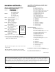
basic MD4000 CONTROLler input/output specifications MD4000 controller connections Located on Main Controller Board Unit #1 C – 24VAC common R – 24VAC hot G – fan (Form A, NO) W – heat (Form A, NO) Unit #2 C – 24VAC common R – 24VAC hot G – fan (Form A, NO) W – heat (Form A, NO) F1-F2 Fire/smoke interface Shipped with jumper installed (a) 48Vdc Back-up power input -24Vdc or –48Vdc -20V to –56V range Local Main sensor, 12-inch leads CU – copper, AG – silver Polarity sensitive Rem 1 Optional
SPECIFICATIONS/FEATURES FOR MD4000-B & -BC Controller ALARMS Inputs Lockout 1 Lockout 2 2, 3 – input from HVAC #1 2, 3 – input from HVAC #2 Outputs Smoke/Fire Form C (SPDT) Lockout 1 Form C (SPDT) Refrigerant alarm HVAC #1 Lockout 2 Form C (SPDT) Refrigerant alarm HVAC #2 Power Loss 1 Form C (SPDT) Power loss HVAC #1 Power Loss 2 Form C (SPDT) Power loss HVAC #2 Low Temp Form C (SPDT) Low temperature alarm High Temp 1 Form C (SPDT) High temperature alarm #1 High Temp 2 Form C (SPDT) H
fire suppression circuit blower operation To disable the MD4000 and shut down both air conditioners, terminals F1 and F2 may be used. The F1 and F2 terminals must be jumpered together for normal operation. A normally closed (nc) set of dry contacts may be connected across the terminals and the factory jumper removed for use with a field-installed fire suppression system. The contacts must open if a fire is detected. See appropriate connection diagram - Figures 1, 2 or 3 for this connection.
General Programming Overview MD4000 Controller Buttons and Function On/Off Button 1. 2. Press and release the On/Off button to turn On controller, 4-character display will illuminate and Lead unit LED will light. Press and release the On/Off button to turn Off controller. Controller will go dark and A/C units will stop. Comfort Button 1. 2. 3. 4. Press and release the Comfort button to change the Cooling Set Point to 72F and the Heating Set Point to 68F for a period of 1 hour.
heating SEQUENCE of OPERATIoN 1. Note: All heating sequences for air conditioners with electric heat or heat pumps will automatically operate in Alternating Lead/Lag/Lead/Lag sequence even if controller is set to Non-Alternating for cooling with or without economizers. 1st stage heating set point is the dead-band (db) below the 1st stage cooling set point (the SP entered into the program). The dead-band is adjustable from 2-40F, and factory default is 27F.
SPECIFICATIONS FOR OPTIONAL REMOTE COMMUNICATION BOARD CB4000 Communication Board Note: If this communication board was not originally factory installed it can be field-installed at anytime. Bard part number is CB4000. It allows remote access via Ethernet, depending upon level of authority assigned, to all functions of the controller system the same as it one was in the building where the controller system is physically installed.
USER PAGE 1. The designated Admin person can assign up to 9 additional users and set-up as Admin, Write or Read authority. 2. User Name and password must be assigned, each must be at least 3 characters long, and are case sensitive. 3. Only “Admin” can add, change or delete users and has access to all controller pages. 4.
controller wiring The MD4000 can be used for controlling two (2) air conditioners with economizers. security (Locking) feature The MD4000 controller can be locked such that unauthorized persons cannot make any changes to temperature set points or any other selectable parameters of the controller system. The ON/OFF and Comfort buttons remain fully active for their normal intent.
TABLE 1 HOOK-UP DIAGRAM SELECTION TABLE — REFERENCE FIGURE 1 SHOWN System Type Model Series MD4000-B Newer ECONWMT Economizer — No Communication Board MD4000-BC Newer ECONWMT Economizer with CB4000 Communication Board A/C with 1-Stage Compressor H**A / H**L 1 2 figure 1 MD4000-B controller connections 1-STAGE (H**a/H**l series) AIR CONDITIONERS WITH (econwmt) ECONOMIZERS AC UNIT 1 3 4 48 47 MD4000 UNIT 1 TERMINAL BLOCK 46 46 45 45 44 44 43 43 42 42 41 MD4000 41 R RED/WHITE R R
figure 2 MD4000-BC controller connections 1-STAGE (H**a/H**l series) AIR CONDITIONERS WITH (econwmt) ECONOMIZERS AND WITH ALARM BOARD & cb4000 COMMUNICATION BOARD AC UNIT 1 3 4 48 47 MD4000 UNIT 1 TERMINAL BLOCK 46 46 45 45 44 44 43 43 42 42 41 MD4000 41 R RED/WHITE R R C BLACK/WHITE C C 27 BLUE Y Y NO YELLOW F F 9 YELLOW/WHITE A A 26 PURPLE 4 4 28 BLUE/WHITE 5 5 30 YELLOW/RED 6 6 10 BROWN/WHITE 7 15 ORANGE 8 8 9 9 UNIT 1 SPYDER ECON DISPLAY 1 DISP
economizer failure alarm alarm wiring Upon failure of either economizer to open on command or close on command, the Economizer Failure Alarm will open normally closed contacts to signal the failure. To utilize this feature, terminals 8 & 9 must be connected to the shelter alarm panel. Alarm relays can be wired for NO (close on alarm) or NC (open on alarm) strategy. A normally closed economizer fail alarm is available on terminals 8 & 9 of the Unit 1 & 2 terminal blocks.
2nd stage cooling alarm EmergencY venTIlatioN sequence This alarm output is available for use if desired. It is important to note that in some installations, due to A/C system sizing and internal heat load, that the secondary (lag) air conditioning unit may be called upon to assist the lead air conditioner some of the time. If this is the case, or possibly when additional heat load is added, using the 2nd stage cooling alarm will cause nuisance alarm conditions.
Figure 3 alarm board connections for normally closed "NC" open-on-alarm strategy important! LED display board is shipped loose to protect it from possible damage during installation of the wiring to main controller board and/or the alarm board. It is polarity sensitive and is keyed so it can only be installed in correct position.
figure 4 alarm board connections for normally open "NO" close-on-alarm strategy IMPORTANT! LED display board is shipped loose to protect it from possible damage during installation of the wiring to main controller board and/or the alarm board. It is polarity sensitive and is keyed so it can only be installed in correct position.
programming instructions To swap lead and lag unit positions, press the ADVANCE button. To enter the Program mode, press the PROGRAM button and release it when the message PROG appears on the display. When in Program mode, the DOWN and UP arrows are used to scroll through the programming steps. A FLASHING display means that the function or choice is “SET”, and the display will alternate between the step function and setting.
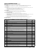
D w See displays above lexan e, trans red, ar 11” h N/A - See Operating Manual N/A - See Operating Manual 27F/15C LEAD N/A - See Operating Manual N/A - See Operating Manual N/A - See Operating Manual N/A - See Operating Manual N/A - See Operating Manual N/A - See Operating Manual N/A - See Operating Manual N/A - See Operating Manual 7961-762 8.
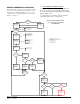
figure 5 parts list description diagram 20 6 18 8 10 1 19 11 14 13 17 3 4 15 5 12 9 Manual 2100-574 Page 22 of 23 7 2 SEXP-648
Parts List Dwg. No. Part No.