3DR Plane INSTRUCTIONS Thank you for purchasing a 3DR Plane! C O NT ENTS 1 2 3 4 5 6 1 2 Fuselage Right wing Left wing Horizontal stabilizer Vertical stabilizer Carbon fiber bar 6 5 3 4
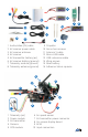
5 2 1 6 4 3 13 9 10 1 2 3 4 5 6 7 8 15 12 11 14 Audio/video (AV) cable AV receiver power cable AV receiver antenna AV receiver AV transmitter battery (air) AV receiver battery (ground) Telemetry module (ground) Telemetry antenna (ground) 9 10 11 12 13 14 15 16 16 Propeller Servo horn screws Ailerons Y cable Micro-USB cable USB extension cable Wing screws Main battery Adhesive Velcro squares 4 5 3 1 2 6 10 1 2 3 4 5 Telemetry (air) Power module AV transmitter Camera GPS module 9 6 7 8 9
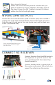
Bixler Assembly Manual Please refer to the assembly manual included with your plane to install main wings, stabilizers, and other parts of the plane’s frame. Use the Y-cable to connect the aileron cables from the left and right wings. WIRING AP M OUTPUTS Connect the servo and electronic speed controller (ESC) wires to APM’s outputs pins in the order indicated below. Connect the white wire to the S pin (top row), the red wire to the + pin (center row), and the black wire to the - pin (bottom row).
PO WE R W I RI N G Motor power connector Connect the power module’s yellow XT60 connectors to the motor and main battery connectors. Connect the AV transmitter battery to the red connector on the transmitter. Main battery AV transmitter battery Power module and transmitter power connector BA L ANCI NG TH E PL AN E Your plane’s center of gravity should be 71 mm from the leading edge.
IN S TAL L S OFT WAR E Mission Planner is free, open-source software providing multiplatform configuration and full-featured waypoint mission scripting for autonomous vehicles. To install Mission Planner on your ground station computer (Windows only), visit ardupilot.com/downloads, select Mission Planner, and select sort by date (short link: goo.gl/Si5grC). Select the most recent (top) MissionPlanner - MSI (Microsoft installer package).
Mission Planner Setup Wizard Launch Mission Planner to explore the capabilities of your autonomous vehicle! Mission Planner will notify you when an update is available; please always run the most current version of Mission Planner. Mission Planner: Flight Data Screen For more information on using Mission Planner or troubleshooting your installation, please visit planner.ardupilot.com. CA L IBRAT E R ADIO CONTR O L Mission Planner’s RC calibration utility teaches APM to work with your RC transmitter.
Open Mission Planner. Connect APM to your computer using the provided micro-USB cable. Windows will automatically install the correct drivers for APM. In Mission Planner, select the COM port for Arduino Mega, set the Baud rate to 115200, and select Connect. 1 2 APM USB port Connect APM to Mission Planner: 3 1 Select Arduino Mega. 2 Select 115200. 3 Select Connect. Turn on your transmitter, and ensure it is set to airplane mode (not helicopter mode).