Preface Preface Sirit’s INfinity 510 User’s Guide is designed to allow you quickly install, configure, and operate your reader. This guide only provides instructions for a basic installation and you should refer to the INfinity 510 Developer’s Guide and Protocol Reference Guide for more detailed programming, configuration, and operation instructions.
1 2 3 4 5 6 Reader Overview Reader Overview Introduction The INfinity 510 is a multiprotocol, multiregional Radio Frequency Identification (RFID) System that operates in the 860 – 960 MHz UHF band. Figure 1 INfinity 510 UHF Reader As shown in the following figure, this high performance reader supports up to four Tx/Rx antennas and one Listen before Talk (LBT) antenna and is equipped with both serial and Ethernet interfaces. Discrete digital inputs and outputs are also provided.
1 2 3 4 5 6 Reader Overview The INfinity 510 is equipped with four status indicators located on the top of the enclosure. These LEDs provide indication for the following: h h h h Sense – Indicates reader has detected a tag in the RF field. Transmit – Indicates the reader’s transmitter is operating (RF on). Fault – Indicates a fault occurred. Power – Indicates that power is applied to the reader. During power up, the LEDs will momentarily flash. 2 INfinity 510 User’s Guide, P1.
1 2 3 4 5 6 Reader Equipment Installation Reader Equipment Installation Mechanical Installation Mounting the Reader The INfinity 510 is equipped with two mounting flanges and slotted keyholes that accept three #8 (M4) mounting screws. Predrill any mounting surface according to the following dimensions. Any mounting surface must be able to support up to four pounds (1.8 kg). 3 3/32" (78.6 mm) (3X) LOCATION FOR #8 Screw (M4) 6 3/16" (157.
1 2 3 4 5 6 Reader Equipment Installation Mounting the Antennas The INfinity 510 supports from one to four antennas in a variety of configurations. One and two-antenna configurations are typical for most conveyor and container tracking. Four-antenna configurations are used for portals and loading dock doorways. The optional Sirit provided antennas are for indoor use only and must be installed on a solid surface or frame to prevent damage or later misalignment.
1 2 3 4 5 6 Reader Equipment Installation Electrical Installation Caution: The INfinity 510 is designed to meet the regulatory requirements in those jurisdictions in which it is offered. Changes or modifications not expressly approved by Sirit Inc for compliance could void the user's authority to operate the equipment. Connecting the Serial Port The INfinity 510 is equipped with one DB9 type RS-232 serial port for communication up to 115 Kbaud.
1 2 3 4 5 6 Reader Equipment Installation Connecting the Ethernet Port Ethernet Cables In most cases, you will connect the INfinity 510 to a network hub or router. However, if you are connecting directly to a PC or other computer, you will need a Crossover Cable that swaps the Tx and Rx signals. The maximum Ethernet cable length is 30 meters. If you are communicating with your reader across a Local Area Network (LAN), connect an Ethernet cable from your hub or router to the RJ-45 connection.
1 2 3 4 5 6 Reader Software Installation Reader Software Installation Installing Reader Configuration Software The INfinity 510 is equipped with a Microsoft Windows PC application called Reader Startup Tool (RST). You can use this application to configure the reader as well as read and display tag data. Install RST 1 To install RST, load your system CD and double-click the Setup.exe file: 2 Press Next> 3 4 Press Next> 5 Press Close when the installation is complete. INfinity 510 User’s Guide, P1.
1 2 3 4 5 6 Reader Configuration Reader Configuration Start RST To start your reader configuration, open the RST application. Open RST 1 From your Windows desktop, select: Start→Programs→Sirit→INfinity510→Reader Startup Tool 8 2 If this is the first time starting the RST application, you may receive a Windows Security Alert. This warning indicates that the firewall is blocking the RST application. 3 If the warning window is hidden under the RST windows, collapse the RST window.
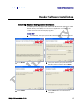
1 2 3 4 5 6 Reader Configuration 4 Press Unblock. 5 Press Refresh on the RST 6 The RST main screen will display any readers currently connected to the network. Initial Reader Setup To configure a specific reader, perform the following: Reader Setup INfinity 510 User’s Guide, P1.04 1 Select the reader on the main RST screen by clicking the button to the left of the reader Mac address. 2 Press the 3 The INfinity 510 Setup Wizard is displayed. button on the RST window.
1 2 10 3 4 5 6 Reader Configuration 4 Press Next>. 5 Enter the Login (admin) and Password. If this is the first time configuring your reader, enter: readeradmin 6 Press Next>. INfinity 510 User’s Guide, P1.
1 2 3 4 5 6 Reader Configuration 7 Select the Region and Sub Region from the pull-downs and press Next>. 8 Select a configuration that most closely resembles your installation and press Next>. 9 Select the protocol of the tags you will be reading and press Next>. Custom Setup If your installation type differs from one of the choices shown in the Setup Wizard, you can always customize your setup later using the embedded web interface capability.
1 2 3 4 5 6 Reader Configuration 10 Select the antennas you will be installing and press Next>. 11 Estimate the number of tags that will be presented to the reader at any one time and press Next>. 12 INfinity 510 User’s Guide, P1.
1 2 3 4 5 6 Reader Configuration 12 Press Finish to complete the initial reader setup. INfinity 510 User’s Guide, P1.
1 2 3 4 5 6 Reader Operation Reader Operation Basic Operation with the Reader Operation Tool The INfinity 510 can be operated either from the RST application or by logging directly into the reader’s embedded web interface. To operate the reader from RST, perform the following: 14 1 From the RST main screen, press Operate Reader. The Reader Operator Tool (ROT) is displayed. 2 Login to the reader. The initial password (Pwd) is readeradmin.
1 2 3 4 5 6 INfinity 510 User’s Guide, P1.04 Reader Operation 4 Select the Tag Performance tab. 5 Press Start. 6 Place your tags in front of the antenna and verify the tags are read and displayed as shown in the previous figure.
1 2 3 4 5 6 Reader Operation Advanced Setup You can also customize the reader setup to more closely match your installation. This is performed by logging directly into the reader’s embedded web interface. You can access this interface from RST. Perform the following: 16 1 From the RST main screen, press Configure. The INfinity 510 Reader Configuration Tool (RCT) is displayed. 2 Select the specific configuration category and follow the instructions. INfinity 510 User’s Guide, P1.
1 2 3 4 5 6 Specifications Specifications Reader Specifications Frequency 860-960 MHz RF Power 10 mW – 2W conducted Connections RS-232, Digital I/O, Ethernet LAN, and WiFi 802.11 (optional) Input Voltage 12 to 24 Vdc, 60W Input Current 2.5A maximum at 24 Vdc 5.0A maximum at 12 Vdc Environmental Specifications Operating Temperature -4° F to 131° F (-20° C to 55° C) Storage Temperature -40° F to 185° F (-40° C to 85° C) Maximum Shock 1 foot (0.
1 2 3 4 5 6 Specifications Power Supply Specifications Input Voltage 100 – 240 Vac Input Consumption 60W maximum Input Frequency 50 – 60 Hz Output Voltage 15 VDC Output Current 4A maximum RS-232 Specifications Connector DB-9S Baud rate 9600 - 115200 (Default = 57600) Parity None Data bits 8 Stop bits 1 Signals Pin 1 Pin 2 Pin 3 Pin 4 Pin 5 Pin 6 Pin 7 Pin 8 Pin 9 CNVSS TXD RXD DTR GND DSR CTS RTSA +3.
1 2 3 4 5 6 Specifications Digital Input/Output Specifications Connector Plugcon 31374112 (1x12) Input 5 to 24 Vdc, 1 to 5 mA, Optically Isolated Output Open Collector (3 to 40 V, 100 mA Max) Signals Pin 2 – DIN1 (Digital Input 1) Pin 3 – DIN2 (Digital Input 2) Pin 5 – DIN3 (Digital Input 3) Pin 6 – DIN4 (Digital Input 4) Pin 1, 4 – Digital input common Pin 8 – DOUT1 (Digital Output 1) Pin 9 – DOUT2 (Digital Output 2) Pin 10 – DOUT3 (Digital Output 3) Pin 11 – DOUT4 (Digital Output 4) Pin 7,12
1 2 3 4 5 6 Safety Instructions Safety Instructions Power Disconnect Device The plug on the power supply cord is intended to be the power disconnect device. As a result, the power source (socket or outlet) shall be located near the equipment and shall be easily accessible. WARNING: FCC Radiation Exposure Statement.