
User's Manual


1
2
3 4 5 6
Reader Equipment Installation
6
INfinity 510 User’s Guide, P1.04
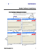
Connecting the Ethernet Port
The maximum Ethernet cable length is 30 meters. If you are communicating
with your reader across a Local Area Network (LAN), connect an Ethernet
cable from your hub or router to the RJ-45 connection. See Figure 2 for
location of the connector. If you are connecting the reader directly to a PC,
you must use a crossover cable. See Note to the left.
Connecting the Antennas
The maximum antenna cable length is 10 meters. Connect the antenna to
antenna port
1. If you are using additional antennas connect them to Ports
2-4. If applicable, connect the LBT antenna to the
Listen port
Caution:
The INfinity 510 UHF Reader is equipped with four (4) RF ports. To prevent reader
damage, active RF ports must be properly terminated with a 50 ohm load or a
functional UHF antenna before power up. UHF Readers are factory configured to
operate on RF port 1. As a result, port 1 must be properly terminated before
initially powering on the reader. Before activating any additional RF ports, they
must also be properly terminated. Never power up the reader unless the
appropriate loads or antennas are connected. Always power down the reader
before removing an antenna or load from an RF port.
The maximum antenna cable length is 10 meters.
Connecting Digital Inputs/Outputs
The INfinity 510 is equipped with a general purpose digital input/output
(I/O) port that provides four optically isolated 5-24 Vdc input signals and
four open-collector output signals. The digital inputs can be used as general
purpose inputs or to trigger the reader for tag reading. These inputs can be
configured to provide an external read trigger from proximity sensors,
photoswitches, or other devices.
The digital outputs can be used as general purpose outputs, to indicate tag
reading activity, or to indicate the reader is transmitting (RF On). The
outputs can also be configured to trigger conveyor gates or other access
control and sorting devices.
Connecting the Power
Connect the 15 Vdc power supply to the reader and connect the power
supply to your 100-240 Vac, 50-60 Hz power source. Allow 30 seconds for
the reader to initialize.
Ethernet Cables
In most cases, you
will connect the
INfinity 510 to a
network hub or
router. However, if
you are connecting
directly to a PC or
other computer,
you will need a
Crossover Cable
that swaps the Tx
and Rx signals.