Replacement Parts and Service Information To Our Customers: This is the brand equipment you ordered. It has been set up and tested in the factory with "Scotch” brand tapes. I technical assistance or replacement parts are needed, call or Fax the appropriate number listed below. Included with each machine is an Instructions and Parts List manual. Technical Assistance: 3M-Matic™ Helpline — 1380, Please provide the customer support coordinator with the machine number, machine type/model and serial number.
Instruction Manual 22A.
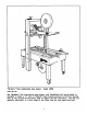
"MI-Matic" 224-S Adjustable Case Sealer Model 18900 Prescriptive The "MI-Natic* 224-5 Adjustable Case Sealer with YAccuGlide® SST Taping Head is deigned to apply a "OY clip of “Scotch” brand Pressure-sensitive Film Box Sealing Tape to the top and bottom center seam of regular slotted containers. The 224-8 is manually adjustable to & wide range of box sizes (see box size specifications).
Receiving And Candling After the machine has been unrated, examine the 22A-5 Case Sealer for damage that might have occurred during transit, 1If damage is evident, file a damage claim immediately with the transportation company and also your 3M Representative. Several machine components are ted down to prevent damage during transit. Remove these before proceeding vita following set-up instructions.
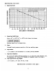
Specifications (Continued) 3. 6. Operating Rate: 30 MAXIMUM OPERATING HATE FOB A GIVEN BOX LENGTH CAN BE OBTAINED BY USE OF GRAN g 28 BELOW, WHITEN 1S BASED ON THE DRIVE BELT Z SPEED DF 75 EFM (0.35 511 [102] (192] (203) [RSFSR (08 a8t} 1457) [508] (558] [610) [660] (7] BOX LENGTH INCHES [mm] Operating Conditions: Use at 40° to 105°F [5° to 40°C] with clean, dry boxes. IMPORTANT SAFEGUARD Machine should not be washed down. Tapes "Scoteh® brand pressure-sensitive film box sealing tapes.
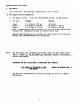
Specifications {Continua) 9. Box Board: 125 to 275 P.8.1, bursting test, single wall flute. 10, Box Weight and Size Capacities A, B. Note: Box weight, filled 5 1bs. [2,3 kg] minimum, 85 1bs, [37 kgl maximum Box size: Minimum Maximum Length 6.0 inches or 150 mm unlimited Width 6.0 inches or 150 mm * 20 inches or 50D mm Height ~ 4.75 inches or 120 mm 20 inches or 500 mm Note: Cartons smaller than 8 inches or 200 mm in width may require more frequent belt replacement because of limited contact ave.
Set-Up Procedure It is commended that the 22A-S Case Sealer be set-up and operated with product before placing it fn the production line. This approach will allow your thorough revive and familiarization with the 22A4-§ before subjecting it and operating personnel to a production situation where time for set-up, adjustments, and operator training usually becomes limited.
Set-LP Procedure (Continued) The following instructions are presented in the order recommended for setting up and installing the 22A-S Case Sealer, as cell as for learning the operating functions and adjustments. Following them step by step will result in your thorough understanding of the machine and an installation in your production line that best utilities the many features built into the 22A-5 Case Sealer.
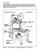
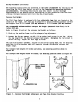
Set-Up Procedure (Continued} Electrical Connection The electrical control box, shown in Figure 1, contains the “On-Off” switch with per-set circuit breaker and can be located on either side of the man conveyor for customer operating convenience. A standard three conductor power cord with plug s provided at the back of the electrical control box for 115 Volt, 60 Hz electrical service. The receptacle providing this service shell be properly grounded.
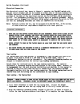
Set-Up Procedure (Continued) Tension Wrap Roller Mansion Roller Applying Mechanism Spring Threading Needle Buffing Applying Roller Roller Blade Guard Knife Blade Figure 3 ~ Tape Threading Diagram Top Taping Head Left Side Kiev Buffing Knife Blade; Rotter Applying Roller Knurled Holier Tension Roller Applying Tension Wrap Roller Y| Changchun sm Spring ‘Tape Adhesive Side S N\ Supply Roll / \ Drum Figure 34 Tape Threading Diagram Bottom Taping Head Left Side View
Set-Up Procedure (Continued) 3. For subsequent tape loading operation, uge the red plastic threading needle and follow the loading procedures from Figure 3B to complete the tape threading. Tape Loading Bottom Taping Head Refer to Pleasure 34 The bottom taping head is loaded and threaded in the same manner as the top taping head. For ease in loading, first remove the bottom taping head from the conveyor bed and follow the top taping head tape loading procedural.
Set-Up Procedure (Continued) Box Size Set-Up and Operation Figure 4 Once both taping heads are loaded with tape, the top taping head cen be positioned for the box height being sealed by means of the height adjustment rank. Turn clockwise to lover head, counterclockwise to¢ raise head. Figure 3 Place box on indeed conveyor with both top and bottom flaps folded and insert under top head skis approximately 2 inches or 50 wm. Lower top head until all flaps ave fully closed.
Set-Up Procedure (Continued) Figure 7 Turn electrical switch to "On® to start drive belts. Move box forward under top taping head until it is taken away by drive belt. If box is hard to move wider head or ls crushed, raise top head slightly. TIf box movement is Jerky or stops under top head, lover top head slightly to edd more pressure between box and drive belts. Note: Top head has unique feature for overstuffed boxes. Top head will raise automatically for this type of condition.
Adjustments Tape Veb Alignment Refer to Figure % The tape drum assembly on each taping head ig per-set to accommodate 2 inch {50 ma] wide tape, but is adjustable to provide alignment of narrower tapes. 1f adjustment is necessary to center the tape width on the center line of the taping head (and therefore box center seam}, make adjustment as follows: 1. Loosen hand knob behind tape drum on tape drum shaft. 2, Turn tape drum shaft in or out to center the tape veb.
Adjustments {Continued) One Vay Tension Roller Assembly The one way tension taller, shown in Figure 34, 1s per-set for normal operation. Should the one way tension roller assembly require replacement, the roller must have 1 pound [0,5 kgl tangential force when turning as illustrated in Figure 12.
Adjustments (Continued) Box Price Belts The two continuously moving box drive belts convey boxes through the tape applying mechanism, The box drive belts are powered by the electric motor through the timing belt/pulley transmission. Tension adjustment of these belts may be required during normal operation. Belt tension must be adequate to positively move the box through the machine and they should run fully on the surface of the pulleys at each end of the frame.
Adjustments (Continued} Center Plate Flat Hd Screw In feed End Box Drive Belt M8 x 12 Socket Hd Screw Conveyor Top: idler Pulley Figure 13 Box Drive Belt Adjustment Frame Bed In feed End B 7 Ibs [35 kg] Pull Force Box Diva Bait Wi unctuous mm] At Mid span In feed End Figure 15 Tension Adjustment Left Side View 135
Maintenance The 22A-5 Case Sealer has been designed for long, trouble free service. The machine well perform best when it receives routine maintenance and cleaning. Machine components that fail or wear excessively should be promptly repaired or replaced to prevent damage to other portions of the machine or to the product, EARNING TURN OFF ELECTRICAL OVER SUPPLY AND DISCONNECT OVER CORD FROM ELECTRICAL SUPPLY BEFORE BEGINNING MAINTENANCE.
Maintenance {Continued) Cleaning 0f The Machine CAUTION NEVER ATTEMPT TO REMOVE DIRT BY LOVING IT OUT WITH COMPRESSED AIR. ‘HIS CAN CAUSE THE DIRT TO BE BLUR INSIDE THE MOTOR, AND SLIDING SURFACES. GRITTY DIRT IN THESE ARRAS CAN CAUSE SERIOUS EQUIPMENT MACADAM. LEVER WASH DON EQUIVALENT. Regular slotted containers produce a great deal of dust and paper chips hen processed or handled in equipment.
Maintenance {Continued}) Lubrication — Mechanical Like most other equipment, the Case Sealer must be properly lubricated to inure long, trouble/free service. Most of the machine bearings are permanently lubricated and sealed and do not need to be greased. The drive motor is lase permanently lubricated and should not require additional lubrication. Figure 17 and 18 illustrate the taping head and frame points which should be lubricated every 250 hours of operation.
Replacement Parts And Service Information Spare Parts It is suggested they the Pillowing spare parts be ordered snd kept ou hand: Qty. Bef, No. 3% Part Buber Description 1 2566-13 78-BOSS-6179-4 Roller Applying i 1567-8 78-8057-6178-6 . Roller -~ Buffing 1 256712 78806082372 Spring Ba tension Top 2 2569-3 78-8060-B419-6 Blade 2.
Attachments Additional information on the attachments listed below is included with the manual except where noted: Part Number Attachment Name 78-8052-6353-1 Box Hold Down Attachment, Model 18300 78-8052-6554-9 Caster Kit Attachment, Model 18500 78-8060-7498-1 Conveyor Extension Attachment, Model 18300 20
SST Taping Bead Assemblies, Model 18900 Replacement Parts Illustrations amd Parts Lists 1. Refer to Taping Head Assemblies figure to find all the parts illustrations identified by Laurel numbers. 2. Refer to the figure or figures to determine the individual parts required and the parts reference number.
Figure 2565 Ref. No. 2565-1 2565-2 25653-3 25654 25655 2565-6 2565-7 2565-8 2565-9 2565-10 2565-11 2565-12 2565-13 2565~14 2565-15 2563-16 2565-17 2565-18 2565-19 256520 3 Part No.
Figure 2566 Ref. No. 23661 2566-2 25663 25664 2566-5 25666 2566-7 2566-8 2566-9 2566-10 2566-11 2566-12 2566-13 2566-14 2566-15 2566-16 2566-17 3M Part No. 78--8060-8225-7 78-8060-8213-3 78806082141 78-8060-8215-8 78-8060-8220-8 78-8060-8217-6 78-8060-8224-0 78-8052-6579-6 78-8017-9074-8 78-8060-8315-6 78-BO60-B354-3 78-8060-8395-8 78-8057-6179-4 78-8060-8204-2 78-8060-8223-2 78801750821 78-8060-8241-4 Description B Entry Gr.
Figure 2567 Ref. No. 3 Part Ro. Description 2567~1 78-8060-8239-8 Exit Gr.
Figure 2569 Ref. No. 2569-1 2569-2 2569-3 25694 25695 2569-6 2569-7 2569-8 2569-9 2569-10 2569-11 2569-12 256913 2569-14 2569-15 2569-16 3¥ Part No.
Figure 2570 Bef. BNo. 2570-1 2570-2 2570-3 2570-4 2570-3 2570-6 2570-7 2570-8 2370-9 2570-10 2570-11 3M Part No.
Figure 2571 Ref. No. 25711 25712 25713 25714 2571-5 2571-6 2571-7 2571-8 2571-% 2571-10 2571-11 257112 2571-13 2571~14 2571-15 257116 2571-17 2571-18 2511-19 2571-20 3M Part No.
Figure 2572 Bef. No. 3M Part No. Description 2572-1 78-8060-8239-8 Exit Gr.
22A-S Case Sealer, Model 18900 Replacement Parts Illustrations and Parts Lists Frame Assemblies 1. 3. Refer to Frame Assemblies figure to find all parts {illustrations identified by figure numbers. Refer to the figure or figures to determine the individual parts required and the parts reference number. The replacement parts list, that follows each {illustration, includes the part number and part description for the parts in the illustration.
Figure 2529 Bef. No. 3% Part No.
Figure 2530 Ref. No. 3X Part No.
Figure 2531 Bef. No. 34 Part No.
Figure 2532 Ref. Mo. 3M Pact No.
Figure 2533 Ref, No. 2533-1 2533-2 2533-3 25334 2533-5 2533-6 2533-7 2533-8 2533-9 2533-10 2533-11 2553-13 3 Part No.
Figure 2335 Ref. No.
Pleasure 2536 Ref. No. 34 Part No.
Figure 2537 Ref. Fo. 3M Peary No. Description 25371 78-8060-8409-7 Support Switch 253722 | 78-8060-8332-1 Screw Soc 25373 78-8060-8410-5 Box Snitch 25374 78-8060-8411-3 Switch PK 25375 78-8060-8412-1 Emergency Stop 25376 Screw -~ Soc 2537-7 78-8060-8797-6 Rasher Plain 4 am, Metric 2537-8 78-8060-8414-7 Nut N4 2537-9 78-8057-5807-1 Cord Grip 2537-10 78-8060-8053-3 Cable 5MT.