Wired Intercom System Performance Series Models 2470 and 2475 Installation Instructions
FCC Information This device complies with part 15 of the FCC rules. Operation is subject to the following conditions: • This device must not cause harmful interference. • This device must accept any interference received including interference that may cause undesired operation. Changes or modifications not expressly approved by the party responsible for compliance could void the user’s authority to operate the equipment. 3M (IPC) 2002. All rights reserved.
Performance Series Front Matter Revision Record Date Revision 2/02/02 4/08/02 4/11/02 4/15/02 4/19/04 01 02 03 A B Reason For Change Preliminary manual released Preliminary second draft Preliminary third draft Manual Released Revisions made i
Performance Series Front Matter Table of Contents System Components .................................................................................... 1 I/O Card and Noise Reduction Module Installation ................................ 2 I/O Card Installation ................................................................................................ 2 3M Model A125, Noise Reduction Module, Installation (Optional).................... 3 Component Placement ...........................................
Performance Series System Components System Components The Performance Series Intercom System consists of: • A minimum of one Model 2475 Station Selector • One Model 2470 Communications Controller • A maximum of 24 Call Stations The system provides two-way audio communication between the Station Selector and the 24 call stations. The system also provides communications between station selectors. It is a single channel, half-duplex, wired system. Figure 1 shows the components. Figure 1.
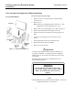
Performance Series I/O Board and Noise Reduction Module Installation I/O Card and Noise Reduction Module Installation I/O Card Installation Be sure the system is powered off! 1. Remove 4 screws on each side of the Communications Controller cover. 2. Remove cover. Note: Insert I/O cards beginning from connector J5. Add additional I/O cards sequentially (J6, J7, etc.). 3. Remove slot cover and mounting screw. Refer to Figure 2. 4. Remove all terminal blocks from edge of I/O card. 5.
Performance Series 3M Model A125, Noise Reduction Module, Installation (Optional) I/O Card and Noise Reduction Module Installation Be sure the system is powered off!. Refer to Figure 3. The optional 3M™ A125 Noise Reduction board (3M part number 78-9236-6453-2) improves the inbound intelligibility of an intercom system by reducing environmental background noise from vehicles, airplanes, noisy intersections, wind, etc. 1.
Performance Series Component Placement Component Placement This section describes placement of the Performance Series Intercom System components: Communications Controller For proper system operation, locate the Communications Controller: 1. Near the conduit termination of the Call Station wiring. 2. Near the power source. 3.
Performance Series Component Placement Call Stations For proper system operation, install the Call Stations in locations: 1. Chosen for ease of use. 2. At least 48 inches above the pavement. Note Local codes may dictate placement of call stations. Figure 5. Suggested Call Station Placement Station Selectors For proper system operation, locate the Station Selectors: 1. At locations chosen for maximum efficiency. 2. On counters, mounted on pedestals, or mounted on walls. 3. In dry and heated areas.
Performance Series Wiring the System Wiring the System Depending on distance, use twisted pair, 14-22 AWG audio cables when wiring the Wired Intercom System, components. Figure 7 shows an overview of the cable types and number of conductors required for each unit. Table 1 shows wire gauge required for different distances between components.
Performance Series Wiring The System Configuration Worksheets Use Configuration Worksheets 1 through 3 (located at the end of this document) to plan and record your system configuration. You can record the system wire locations, wire color scheme, and program settings on the worksheets. Store the worksheets inside the cover of the Communications Controller. Wiring Call Stations Call Station wiring consists of the following for a one-button, four-wire system: • 2 Speaker wires.
Performance Series Initializing the System Wiring Communications Controller Figure 9. Connecting P3 to Communications Controller Refer to Configuration Worksheets 2 and 3 to determine the specific wires and connections to be made.
Performance Series Initializing the System Initializing the System System Mode Selection: Before starting the system Initialization process, you must determine the mode of operation. Check the number of speakers at each Multiple Product Dispenser (MPD). Typically, each active side of the MPD is identified as a separate pump: Number of Speakers at MPD Mode of Operation to Use 1 Island Mode 2 Pump Mode Table 2. Determining Mode of Operation Figure 10.
Performance Series Initializing the System ! Important 1. Initialization will erase all memorized parameters and restore factory default values. 2. If Pump Mode (factory default) is desired, initialization is not required. 3. If software is upgraded, the system must be re-initialized. Initialization instructions for Pump Mode (factory default) Init PUMP Mode ‘TALK’ = Yes 1:PUMP MODE Pump mode assigns each Call Station to a single number (1 through 24).
Performance Series Programming the System Programming the System ! Important If you have not selected the mode of operation (Pump or Island) do so now! See System Mode Selection. Programming State To program the Performance Series Intercom System, it is necessary to put the system in the programming state. From this state, the entire system is configured and all memorized parameters are adjusted. To enter the programming state, simultaneously: Press and hold the STD BY key.
Performance Series Programming the System Error Message ! E R R O R ! NO COMMUNICATION Parameter Selection 01:Selector ID # {01} 02:Controller {D2400 1-Chnl} 03:Max Stations {24} 04:Silence Calls {Off} 05:Alert Volume {08} The system will display one error message: No Communication. This message occurs when there is no communications between the Station Selector and Communications Controller. To correct this: • Be sure Communications Controller is powered on.
Performance Series 07:VOX Enable {Off} 08:VOX Sensitive {15} 09:Talk Vol{10} S=01 PUMP # 01 10:Music Volume {08} 11:Priority{Off} S=xy: User Name Programming the System A value (On, Off). Default = Off. Enables the VOX (Voice Operated Transmission) feature. A number (1 to 15 inclusive). Default = 15 (most sensitive). Adjust this value to accommodate the ambient noise level at the Station Selector location. Use a lower value for a higher noise environment. A number (1 to 15 inclusive). Default = 08.
Performance Series Programming the System 16:Music {On } S=xy: User Name A value (On, Off) for each Call Station. Default = On. Off will mute music at selected Call Station(s). This parameter is used to disable music at any Call Station. This parameter is used to disable music or messages at any Call Station. 17: All Call {On } S=xy: User Name A value (On, Off) for each Call Station. Default = On. Off will disable All Call broadcasts at selected Call Station(s).
Performance Series Keypad Function Definitions (for Text entry) (Programming State) Programming the System Key functions are defined below. Key 1 2 3 4 5 6 7 8 9 MENU 0 T A L K Function HOLD (Shift) Shifts between upper and lower case for text data. UP ARROW Increments data by 1. Fields wrap around. DOWN ARROW Decrements data by 1. Fields wrap around. 1 Enters the digit 1 for numeric entry. Enters the following for text entry: SP-389C Figure 12.
Performance Series Programming the System Key 6 Function Enters the digit 6 for numeric entry. Enters the following for text entry: Unshifted Shifted 7 6 6 _ | S s T t U u 7 7 . ! V v W w X x 8 8 & @ 9 9 ’ “ 0 0 < > Enters the digit 9 for numeric entry. Enters the following for text entry: Unshifted Shifted 0/MENU R r Enters the digit 8 for numeric entry. Enters the following for text entry: Unshifted Shifted 9 Q q Enters the digit 7 for numeric entry.
Performance Series Adjusting the System Adjusting the System Inbound Audio Volume Level To set the inbound audio volume level: 1. Ask an attendant to stand at a Call Station and push the incoming call button for your Station Selector. 2. Answer the call by pressing the TALK button. 3. As the attendant talks, adjust the up/down arrows on the Station Selector keypad to reach a desirable level.
Performance Series Adjusting the System Outbound Music/Messaging Volume Level (Only for systems that use Music/Messaging) To set the outbound Music/Messaging volume level: 1. Follow the directions under the section Programming the System to put the Station Selector in programming mode 2. Locate the Music Volume parameter and follow the instructions in that section. Testing the Functions Perform the following tests after installing the Performance Series D-2400 Intercom System: 1.
Performance Series Configuration Worksheets Configuration Worksheets 19
Performance Series Configuration Worksheets 20
Performance Series Configuration Worksheets 21
Commercial Care Division Food Service Business 3M Center St. Paul, MN 55144-1000 Printed in U.S.A.