INSTALLATION AND OPERATING INSTRUCTIONS CFSM1254 WATER SOFTENER Installer: Please leave this manual with owner/operator. Owner/Operator: Please retain for operation and future maintenance instructions.
SAFETY INFORMATION Read, understand, and follow all safety information contained in these instructions prior to installation and use of the CFSM1254 Water Softener. Retain these instructions for future reference. Failure to follow installation, operation and maintenance instructions may result in property damage and will void warranty. Intended use: The CFSM1254 Water Softener is intended for use in softening water and has not been evaluated for other uses.
IMPORTANT NOTES TABLE OF CONTENTS • The system should be installed on cold water lines only. • Failure to follow instructions will void warranty.
Check Your Pumping Rate and Water Pressure: Two water system conditions must be checked carefully to avoid unsatisfactory operation or equipment damage: 1) MINIMUM water pressure required at the water softener inlet is 20 psi (1.4 bar). IF WATER PRESSURE IS OVER 80 psi (552 kPa), A PRESSURE REDUCING VALVE MUST BE INSTALLED IN THE WATER SUPPLY LINE AHEAD OF THE WATER SOFTENER. CAUTION To reduce the risk associated with property damage due to water leakage: • Do not install if water pressure exceeds 100 psi.
Facts to Remember While Planning Your Installation: 1) All installation procedures MUST conform to local and state plumbing codes. 2) Remember that the water softener INLET is attached to the pipe that supplies water (i.e. runs to the pump) and the OUTLET is the line that runs toward the water heater. CAUTION To reduce the risk associated with property damage due to plugged water lines: • Pay particular attention to correct orientation of control valve. Water flow should match arrow on control valve.
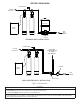
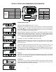
SECTION 2: INSTALLATION FILTERED WATER FILTERED SOFT WATER PRESSURE TANK BRINE MAKER RAW WELL WATER SOFTENER FILTER PRESSURE SWITCH. STANDARD WELL INSTALLATION FILTERED WATER FILTERED SOFT WATER WATER FOR LAWN SPRINKLERS OR OTHER HIGH DEMAND METER BRINE MAKER SOFTENER RAW WATER FILTER CHECK VALVE PUBLIC WATER SUPPLY INSTALLATION Figure 1.
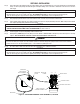
SECTION 2: INSTALLATION Step 1) Remove the unit from the shipping box and remove all packaging. Ensure no freight damage has occurred since shipment from our manufacturing facility. Locate the parts package and install the bypass and adapter fittings on the control valve to facilitate the connection to the customer’s water supply. CAUTION To reduce the risk associated with property damage due to water leakage: • On plastic fittings, never use pipe sealant or pipe dope.
Step 7) Attach DRAIN LINE to DRAIN LINE FITTING. To prevent back pressure from reducing flow rate below minimum required for backwash, DRAIN LINE MUST be sized according to run length and relative height. Be careful not to bend flexible drain tubing sharply enough to cause “kinking” (if kinking occurs DRAIN LINE MUST BE REPLACED). Typical examples of proper DRAIN LINE diameters are: 1) 1/2” ID up to 15 ft. when discharge is lower than INLET. 2) 5/8” ID up to 15 ft.
SECTION 3: CONTROL VALVE PROGRAMMING AND REGENERATION Grains Capacity/lb NaCl 6,000 to 3,000 2 Less than 7.5 Lbs NaCl/cu ft resin Cycle Time in Minutes WS1 & WS 1.
Step 1 Diagnostics Step 2 (Step 1) Press or simultaneously for 3 seconds. If screen in step does not appear in 5 seconds the lock on the valve is activated. To unlock press, , NEXT, , and SET CLOCK in sequence, then press NEXT and simultaneously for 3 seconds. (Step 2) Days, since last regeneration: This display shows the days since the last regeneration occurred. Press the NEXT button. Press REGEN to exit Diagnostics.
Step 1 Step 1 Step 2 Valve History (Step 1) Press or simultaneously for 3 seconds and release. Then press and simultaneously and release. If screen, to the left, does not appear is 5 seconds the lock on the valve is activated. To unlock press , NEXT, and SET CLOCK in sequence, then press and . Then press and simultaneously and release. (Step 2) Software Version: This display shows the software version of the valve. Press the NEXT button to go to the next step or press REGEN to exit Valve History.
User Display Settings General Operation When the system is operating, one of two displays will be shown. Pressing NEXT will alternate between the displays. One of the displays is always the current time of day. The second display is one of the following: days remaining or gallons remaining. Days remaining is the number of days left before the system goes through a regeneration cycle. Capacity remaining is the number of gallons that will be treated before the system goes through a regeneration cycle.
SECTION 4: MAINTENANCE Replenishment of Salt Supply: The salt storage capacity of the brine tank is approximately 135 lbs. (61 kg). During each regeneration a specific amount of salt is consumed, thus requiring its periodic replenishment (the frequency and salt dosage level is dependent on the regeneration schedule). Always replenish salt before the supply is exhausted for a continuous supply of softened water. Type of Salt to Use: Any type of water softener salt may be used.
SECTION 5: CONTROL VALVE TROUBLESHOOTING GUIDE Problem Possible Cause A. AC Adapter unplugged Solution A. Connect power B. No electric power at outlet B. Repair outlet or use working outlet C. Problem with AC Adapter C. Replace AC Adapter D. Problem with PC Board D. Replace PC Board A. Switched outlet A. Use uninterrupted outlet B. Power outage B. Reset time of day C. Problem with PC board C. Replace PC board A. Bypass valve in bypass position A. Put bypass valve in service position B.
SECTION 5: CONTROL VALVE SERVICE INSTRUCTIONS Drive Assembly: Remove the valve cover to access the drive assembly. IMPORTANT NOTE: Disconnect the power source plug (black wire) from the PC board prior to disconnecting the motor or water meter plugs from the PC board. The power source plug connects to the four-pin jack. The motor plug connects to the two-pin jack on the left-hand side of the PC board. The water meter plug (grey wire) connects to the three-pin jack on the far right-hand side of the PC board.
Reattach the main piston to the drive cap assembly. Reattach the regenerant piston (if needed) to the main piston. Do not lubricate the piston rod, main piston or regenerant piston. Lubricant will adversely affect the clear lip seals. Reinsert the drive cap assembly and piston into the spacer stack assembly and hand tighten the drive cap assembly.
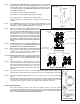
the left side of the control valve. Pliers may be used to unscrew the nut if necessary. With the nut removed, a slot at the top of the water meter is visible. Twist a flat blade screwdriver in the slot between the control valve body and the meter. When the meter is part way out it is easy to remove the water meter from the housing. Once the water meter is removed from the control valve body, gently pull forward on the turbine to remove it from the shaft. Do not use a wire brush to clean the turbine.
SECTION 5: SYSTEM TROUBLESHOOTING GUIDE Problem 1. Hard water (unit not using salt; liquid level in brine tank NOT too high) 2. Hard water (unit using salt; liquid level in brine tank NOT too high) 3. Liquid level in brine tank TOO high 4. System regenerates at wrong time of day 5. Water continuously flows to drain Cause Solution A. Electrical service to unit interrupted A. Assure permanent electrical service (check fuse, plug, pull chain, or switch) B. Timer not working. B.
SECTION 6: SPECIFICATIONS AND OPERATING DATA ITEM CFSM1254 Nominal Media Vol. Ft3 High Capacity Cation Exchange Media 2.5 Salt Dosage, Lbs. Factory Setting 24 Softening Capacity, Grains At Factory Salt Setting 62,200 Flow Rates Continuous (no duration limit) 9 Service Flow Rate 10 At 15 psi Pressure Loss 11.9 Pressure Loss, psi At Continuous Flow 10 Service Flow Rate 12 Regeneration Flow Rates, gpm Backwash 3.2 Brine Draw 0.56 Slow Rinse 3.2 Rapid Rinse 3.2 Brine Refill 0.
Section 7: PARTS COMPONENT PARTS LIST REF No. DESCRIPTION CFSM1254 1 Control Valve W12M320-5B3-0M 2 Adapter Assembly, Flange-Thread (Incl. Ref 3) FA45TX 3 O-Ring ORG-234 4 Clamp Assembly (Incl. Ref 3) FC45XX 5 Media Tank (Incl.
Section 7: PARTS COMPONENT PARTS LIST Front Cover and Drive Assembly Drawing No. Order No. Description Quantity 1 V1375-01 WS1 Front Cover 1 2 V3107-01 WS1 Motor 1 3 V3106-01 WS-1 Drive Bracket & Spring Clip 1 4 V3108 WS1 PC Board 1 V3002 WS1 Drive Assy* 1 Not Shown V3168 WS1 AS Adapter 110V-12 V 1 Not Shown V3168-01 WS1 AC Adapter Cord Only 1 * Drawing number parts 2 through 6 may be purchased as a complete assembly, part V3002.
Section 7: PARTS COMPONENT PARTS LIST Drive Cap Assembly, Downflow Piston, Regenerant Piston and Spacer Stack Assembly Drawing No. Order No.
Section 7: PARTS COMPONENT PARTS LIST Injector Cap, Injector Screen, Injector, Plug and O-Ring Drawing No. Order No. Description 1 V3176 Injector Cap 1 2 V3152 O-ring 135 1 3 V3177 Injector Screen 1 4 V3010-1Z Injector Assy.
Section 7: PARTS COMPONENT PARTS LIST Refill Flow Control Assembly Drawing No. Order No. Description Quantity 1 H4615 Elbow Locking clip 1 2 JCP-P-6 Polytube insert 3/8” 1 3 JCPG-6PBLK Nut 3/8” 1 4 H4613 Elbow Cap 3/8” 1 5 V3163 O-ring 019 1 6 V3165-01* BLFC Retainer Assembly** 1 7 V3182 BLFC 1 Not Shown H4650 Elbow 1/2” with nut and insert Option * Assembly includes V3182 BLFC. ** Includes drawing #7.
Section 7: PARTS COMPONENT PARTS LIST Drain Line - 3/4” Drawing No. Order No. Description 1 H4615 Elbow Locking Clip 1 2 PKP10TS8-BULK Polytube insert 5/8 1 3 V3192 Nut 3/4 Drain Elbow 1 4 V3158-01 Drain Elbow 3/4 Male 1 5 V3163 O-ring 019 1 6 V3159-01 DLFC Retainer Assembly 1 7 V3162-032 DLFC 3.2 gpm for 3/4” One DLFC must be used if 3/4 fitting is used Wa ter Flow Proper DLFC orientation directs water flow towards the washer face with rounded edge.
Section 7: PARTS COMPONENT PARTS LIST Water Meter and Meter Plug Drawing No. Order No.
Section 7: PARTS COMPONENT PARTS LIST Order No: V3007-02 Description: Fitting 1” Brass Sweat Assembly Order No: V3007-03 Description: Fitting 3/4” Brass Sweat Assembly Drawing No. Order No. Description Quantity Drawing No. Order No.
Section 7: PARTS COMPONENT PARTS LIST Bypass Valve Drawing No. Order No. Description Quantity 1 V3151 Nut 1” Quick Connect 2 2 V3150 Split Ring 2 3 V3105 O-ring 215 2 4 V3145 Bypass 1” Rotor 2 5 V3146 Bypass Cap 2 6 V3147 Bypass Handle 2 7 V3148 Bypass Rotor Seal Retainer 2 8 V3152 O-ring 135 2 9 V3155 O-ring 112 2 10 V3156 O-ring 214 2 V3191-01 Vertical Adapter Assembly Order No.
Section 7: PARTS COMPONENT PARTS LIST Wrench (Order No. V3193-01) Although no tools are necessary to assembly or disassemble the valve, the wrench (shown in various positions on the valve) may be purchased to aid in assembly or disassembly.
LIMITED WARRANTY For any warranty questions, please refer to the enclosed warranty card or call 1-800-222-7880 or mail your request to: CUNO Incorporated 400 Research Parkway Meriden, CT 06450 © 2009 3M Company. All rights reserved. 3M is a trademark of 3M Company. INSTR4330 0709 CUNO Incorporated 400 Research Parkway Meriden, CT 06450, USA Toll Free: 1.888.218.CUNO Worldwide: 203.237.5541 Fax: 203.238.8701 www.cunofoodservice.