# Convenience Store Intercom System Model D-2400 Installation Instructions
FCC Information This device complies with part 15 of the FCC rules. Operation is subject to the following two conditions: • • This device must not cause harmful interference. This device must accept any interference received including interference hat may cause undesired operation. Changes or modifications not expressly approved by the party responsible for compliance could void the user’s authority to operate the equipment.
M Model D-2400 Front Matter Revision Record Date Revision 5/00 6/00 7/00 7/00 7/00 8/00 1/01 01 02 03 04 A B C Reason For Change Preliminary manual released. Incorporated changes from Revision 01. Incorporated changes from Revision 02.
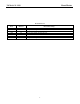
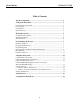
3M Model D-2400 Front Matter Table of Contents System Components .................................................................................... 1 Component Placement ................................................................................ 3 Communications Controller.....................................................................................3 Power Supply ...........................................................................................................3 Call Stations .......
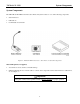
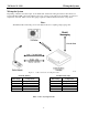
3M Model D-2400 System Components System Components The 3M™ Model D-2400 Convenience Store Intercom System consists of one of the following components: • Station Selectors • Call Stations • Communcations Controller Figure 1. Model D-2400 Convenience Store Intercom System Components Material Required (not supplied) • Assortment of screws, anchors, and cable clamps • Sufficient twisted pair sets of audio cable to connect other components such as Station Selector, Call Staions, etc. See Figure 1.
3M Model D-2400 System Components This page intentionally left blank.
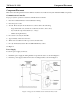
3M Model D-2400 Component Placement Component Placement This section describes placement of the 3M™ Convenience Store Intercom System, Model D-2400, components: Communications Controller For proper system operation, locate the Communications Controller: 1. Near the conduit termination of the Call Station wiring. 2. Near the power source. 3.
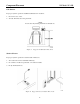
3M Model D-2400 Component Placement Call Stations For proper system operation, install the Call Stations in locations: 1. Chosen for ease of use. 2. At least 48 inches above the pavement. ü Note Local codes may dictate placement of call stations. Figure 3. Suggested Call Station Placement Station Selectors For proper system operation, locate the Station Selectors: 1. At locations chosen for maximum efficiency. 2. On counters, mounted on pedestals, or mounted on walls. 3. In dry and heated areas.
3M Model D-2400 Wiring the System Wiring the System Depending on distance use twisted pair, 14-22 AWG audio cable when wiring Convenience Store Intercom System, Model D-2400, components. Figure 5 shows an overview of the cable types and number of connectors required for each unit. Table 1 shows wire gauge required for different distances between components. Note: The RS485 cable carries DC power for the Station Selectors, requiring a larger gauge wire. Figure 5.
3M Model D-2400 Wiring the System Configuration Worksheets Use Configuration Worksheets 1 through 3 (located at the end of this document) to plan and record your system configuration. You can record the system wire locations, wire color scheme, and program settings on the worksheets. Store the worksheets in the inside cover of the Communications Controller using the service envelope provided.
3M Model D-2400 Programming the System Programming the System Program the system to conform to your planned configuration and desired operation. Hardware (Jumpers) Select Call Station(s) to receive ALL CALL and music/messaging during STANDBY mode. (A closed jumper turns ALL CALL and music/messaging OFF. An open circuit jumper turns ALL CALL and music/messaging ON.) 1. Use the appropriate jumper to select ALL CALL and music/messaging for each call station. 2.
3M Model D-2400 Programming the System Programming the Selector Programming State To program the D-2400, it is necessary to put the system in the programming state. From this state, the entire system is configured and all memorized parameters are adjusted. To enter the programming state, simultaneously: Press and hold the STD BY key. Enter the numeric code: 97531.
3M Model D-2400 Keypad Function Definitions (Programming State) Programming the System Key functions are defined below. Key 1 2 3 4 5 6 7 8 MENU 0 9 T A L K Function HOLD (Shift) Shifts between upper and lower case for text data. UP ARROW Increments data by 1. Fields wrap around. DOWN ARROW Decrements data by 1. Fields wrap around. 1 Enters the digit 1 for numeric entry. Enters the following for text entry: SP-389C Unshifted Shifted Figure 6.
3M Model D-2400 Programming the System Key 6 Function Enters the digit 6 for numeric entry. Enters the following for text entry: Unshifted Shifted 7 6 6 _ | S s T t U u 7 7 . ! V v W w X x 8 8 & @ 9 9 ’ “ 0 0 < > Enters the digit 9 for numeric entry. Enters the following for text entry: Unshifted Shifted 0/MENU R r Enters the digit 8 for numeric entry. Enters the following for text entry: Unshifted Shifted 9 Q q Enters the digit 7 for numeric entry.
3M Model D-2400 Error Message ! E R R O R ! NO COMMUNICATION Programming the System The system will display one error message: No Communication. The message occurs when there is no communications between the Selector and Controller. To correct this: 1. 2. Parameter Selection 01:Selector ID # {01} 02:Max Stations {16} 03:Alert Volume {08} Be sure Controller is powered on. Be sure pins 2 and 3 of J22 on the Controller are connected to pins 2 and 3 of J8 on the Selector. Polarity must be correct.
3M Model D-2400 Programming the System 07:Priority{Off} S=xx: User Name A value (Off, 1 to 16 inclusive). Priority station #, always moves to top of queue. On or Off. Enables the 30 second station connection time out. Default = On. 08:Auto Standby 09:Station Name S=xy: User Name 10:Sync All Data ‘T A L K’ = Yes Are You Sure ? ‘T A L K’ = Yes 11:Software Rev. Se=a.bc Con=x.
3M Model D-2400 Adjusting the System Adjusting the System Communications Controller You must remove the cover from the Communications Controller to perform the following adjustments. Outbound ALL CALL Volume Level To set the outbound ALL CALL Volume Level: 1. Ask another attendant to stand near a Call Station that is not in use. 2. Press and hold the ALL CALL button on the Station Selector to make the connection to the Call Stations. 3.
3M Model D-2400 Adjusting the System Outbound Music/Messaging Level (Only for Systems That Use Music/Messaging) To set the outbound Music/Messaging level, do the following: 1. Ask another attendant to stand near a Call Station that is not in use and has Music/Messaging activated. (See the Communications Controller Hardware Section on Page 7 for details on how to activate Music/Messaging for a Call Station.) 2. Determine if the Music/Messaging volume is low, satisfactory, or high. 3.
3M Model D-2400 Adjusting the System To set the VOX sensitivity level: 1. Follow the directions under the section Programming the Selector to put the Selector in Programming mode. 2. Locate the VOX Enable screen and be sure it is set to ON. 3. Locate the VOX Sensitive screen and press the right-arrow key to edit the value. 4. Use the up/down arrow keys to adjust sensitivity: • • 5. The up arrow key increases the sensitivity (lengthens the distance from the microphone to the attendant).
3M Model D-2400 Adjusting the System This page intentionally left blank.
3M Model D-2400 Training Users Training Users Train users of the Convenience Store Intercom System, Model D-2400, by performing the following steps: 1. Powering the system up (it should remain on). 2. Answering a call. 3. Initiating a call. 4. Adjusting inbound volume. 5. Operation of any applicable equipment. - Remote Microphone. - Music/Message unit.
3M Model D-2400 Training Users This page intentionally left blank.
3M Model D-2400 Configuration Worksheets Configuration Worksheets 19
3M Model D-2400 Configuration Worksheets CONFIGURATION WORKSHEET 2 COMMUNICATIONS CONTROLLER - STATION SELECTOR RS-485 and OTHER CONNECTIONS COMMUNICATIONS CONTROLLER IMPORTANT RECORD SETTINGS AND WIRE COLORS. STORE THIS DOCUMENT IN THE COMMUNICATIONS CONTROLLER. D - 2400 TO POWER SETTINGS Max Station Priority Auto Standby (1 - 16) (Off, 1, ...
3M Model D-2400 Configuration Worksheets CONFIGURATION WORKSHEET 3 COMMUNICATIONS CONTROLLER-STATION SELECTOR AUDIO CONNECTIONS IMPORTANT: RECORD WIRE COLORS. STORE THIS DOCUMENT IN THE COMMUNICATIONS CONTROLLER.
3M Food Services Trade Department 3M Center St. Paul, MN 55144-1000 Printed on recycled paper. Printed in U.S.A.