EX II 3000SP Controller Reference Guide 3M Touch Systems Read and understand all safety information contained in this document before using this product.
EX II 3000SP Controller Reference Guide The information in this document is subject to change without notice. No part of this document may be reproduced or transmitted in any form or by any means, electronic or mechanical, for any purpose, without the express written permission of 3M Touch Systems. 3M may have patents or pending patent applications, trademarks, copyrights, or other intellectual property rights covering subject matter in this document.
Contents About This Manual What You Need to Know........................................................................ 5 Important Safety Information.................................................................. 5 3M Touch Systems Support Services ..................................................... 6 3M Touch Systems Worldwide Offices.................................................. 7 Chapter 1 Integrating the EX II 3000SP Controller Overview of the EX II 3000SP Touch Screen Controller...........
EX II 3000SP Controller Reference Guide Reset ...................................................................................................... 30 Restore Defaults .................................................................................... 31 Unit Type............................................................................................... 32 Appendix A EX II 3000SP Controller Specifications Technical Specifications ...................................................................
About This Manual 3M Touch Systems offers several advanced touch screen controllers designed for reliability and easy installation. Each controller provides superior performance and delivers excellent stability, sensitivity, accuracy, and fast response. This reference manual, directed to developers of touch screen systems, provides installation and configuration information for the 3M Touch Systems EX II 3000SP TouchPen touch screen controller.
EX II 3000SP Controller Reference Guide Intended Use The EX II 3000SP TouchPen controller was designed to enable touch in conjunction with other 3M Touch Systems products and was tested to replace an existing controller. This controller is intended for indoor use only and is not designed for use in hazardous locations. WARNING To avoid the risk of fire and/or explosion which could result in serious injury or property damage: ! Do not install or use this product in a hazardous location.
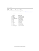
About This Manual 7 3M Touch Systems Worldwide Offices All offices can be reached through the website: http://www.3mtouch.com/.
CHAPTER 1 Integrating the EX II 3000SP Controller The 3M Touch Systems EX II 3000SP controller provides a drop-in replacement for the entire family of TouchPen controllers with all the improved features of the EX II chipset including wide dynamic range, increased noise immunity, wide operating temperature stability, reprogrammability using software utilities and inherent APAC (ungrounded) capability.
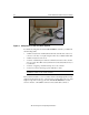
EX II 3000SP Controller Reference Guide Figure 1 Components of the TouchPen System To effectively integrate and test the EX II 3000SP controller, you will need the following items: • A 3M Touch Systems TouchPen (P/N 69-502 with 7311420 cable extension to connect to controller). A complete integration kit is also available: P/N 69-900. • A 3M Touch Systems touch screen • A method of establishing the serial data communication between the controller and your system.
Integrating the EX II 3000SP Controller 11 Figure 2 EX II 3000SP Connector Locations Figure 3 EX II 3000SP Overall Dimensions Establishing the Data Connection The EX II 3000SP controller requires that an RS-232 serial communication cable be attached to connector JP3. You can use a 3M Touch Systems RS-232 cable (P/N 7311273). One end of this cable plugs into the RS-232 connector (JP3) on the EX II 3000SP controller. The other end, which has a 9-pin D connector, plugs into a serial COM port on your PC.
EX II 3000SP Controller Reference Guide Table 1 COM Cable for EX II 3000SP Controller PC Side (9-Pin D) Wire Controller Side (7-Pin Molex) JP3 Pin 1 2 3 4 5 6 7 8 9 Shell NC Color Pin NC 4 3 NC 2 NC NC NC NC NC 1 White Red Black Description Receive data (RXD) Transmit date (TXD) Ground (also connects to grey wire) +12V to orange wire Mounting the Controller The controller should be mounted on the chassis inside the monitor.
Integrating the EX II 3000SP Controller 13 Mounting the Touch Screen There are several methods for mounting the touch screen depending on your application (CRT displays or flat panel displays, each in a variety of sizes). If you need instructions or recommendations from 3M Touch Systems on how to incorporate a touch screen into your OEM design, refer to the Touch Screen Kits Installation Guide (P/N 19-215) or the Flat Panel Display Integration Reference Guide (P/N 19-250).
EX II 3000SP Controller Reference Guide When you power-up the unit, the LED is bright until the controller start-up sequence is completed. Following start-up, the LED becomes dim and remains dim as long as you do not touch the sensor. When you touch the sensor, the LED becomes bright. A flashing (or blinking) LED during power-up indicates the controller’s power-on self-test failed. Refer to Table 2 for a description of each error code.
Integrating the EX II 3000SP Controller 15 TouchWare also includes a control panel for setting your touch screen preferences and a diagnostic utility. If you are experiencing problems with the touch screen, you can use the diagnostic utilities provided to locate the touch screen controller and test the touch screen. For more information on connecting your cables and installing and using the touch screen control panel and utilities, refer to the TouchWare User’s Guide (19-224).
CHAPTER 2 EX II 3000SP Controller Communications This chapter discusses the fundamentals of communicating with the EX II 3000SP controller. Firmware commands are usually issued by a driver or utility program on the host system, however developers can enter these commands directly.
EX II 3000SP Controller Reference Guide Data Format Data format refers to the type of packet the controller uses to send the X/Y touch coordinates to the host system. Format Tablet is the format for the EX II 3000SP controller operating at 8 data bits only. • Format Tablet uses only 5 bytes per point and provides a rapid response time. • Format Tablet includes a status byte.
EX II 3000SP Controller Communications 19 Commands to the controller are sent on the signal Receive Data (RXD) line as a serial data stream. For each command it receives, the controller sends a response to the host on the signal Transmit Data (TXD) line also as a serial data stream. Sending Commands to the Controller When you send a command to the controller, you must use the correct command format.
EX II 3000SP Controller Reference Guide Note: The following descriptions of header, response, and terminator, use 3M Touch Systems terminal emulator key sequences. The format of controller responses varies depending on the terminal emulation mode you are using. The header is the first character in the response string and is the ASCII start-of-header control character SOH. The hexadecimal code for the ASCII SOH control character is 01.
EX II 3000SP Controller Communications 21 Summary of Firmware Commands Developers may use this information when writing touch applications, developing custom drivers or touch configurations, or testing their touch systems. Developers can use firmware commands to initialize the controller, select operating modes, specify data formats, and execute diagnostic functions. Most touch screen users do not have to use firmware commands to use their touch systems.
EX II 3000SP Controller Reference Guide Table 3 Firmware Commands for EX II 3000SP Development Command Name Code Description Pen or Finger The controller recognizes both TouchPen and finger touch. This is the default setting. PF Calibrate Extended CX Initiates an interactive, two-point calibration. Calibrate Raw CR Collects the raw X and Y coordinates prior to normal scaling, linearization, and filtering process.
EX II 3000SP Controller Communications 23 Calibrate Extended Syntax: Description: CX Initiates an interactive, two-point calibration. During the calibration process, you define the active area of the touch screen by mapping locations to an absolute X/Y coordinate system. You touch two target areas on the screen. Touching the target areas sends the X/Y coordinates for those touch points to the controller. The controller calculates all other touch points based on these two points.
EX II 3000SP Controller Reference Guide (1023, 0) [1024, 1024]* (0, 0) (560, (895,420) 96) Upper Right Calibration Target X = 1023 – (1024 x 1/8) = 1023 – 128 = 895 Y = 0 + (768 x 1/8) = 0 + 96 = 96 (128, 671) (80, 60) [1024, 0]* (0, 767) [0,0]* Lower Left Calibration Target X = 0 + (1024 x 1/8) = 0 + 128 = 128 Y = 767 - (768 x 1/8) = 767 - 96 = 671 *The coordinates are in video terms, with the origin (0, 0) in the upper left corner of the screen.
EX II 3000SP Controller Communications No Response 25 2 Indicates that the user did not touch the target long enough to provide an accurate calibration point. Calibrate Raw Syntax: Description: CR Allows the collection of raw (signed) X and Y coordinates prior to the normal scaling, linearization, and filtering processes.
EX II 3000SP Controller Reference Guide Table 5 describes the meaning of the bits in the status byte (Byte 1). Table 5 Calibrate Raw Status Bits Bit Description Values S0 – S5 S6 Reserved Proximity (touch state) S7 Packet synchronization — 1 = Touch screen is being touched (a touchdown or a continued touch). 0 = Touch screen is not being touched (a touch liftoff or inactive).
EX II 3000SP Controller Communications 27 To terminate Format Raw, issue a Reset command. The controller may return several bytes of data between the time you issue a Reset command and when the controller receives it. You can either scan the data stream for the Reset acknowledgment, or you can ignore the response to the first Reset command and then issue a second Reset after approximately 10 seconds has passed. Use the Format Raw command for diagnostics.
EX II 3000SP Controller Reference Guide Format Tablet Syntax: FT Description: Outputs the X/Y touch coordinate data in a 5-byte packet. The packet includes 1 status byte and 4 bytes of binary X/Y coordinate data. The protocol also establishes the X and Y coordinate output as 14 binary bits providing a range of 0 to 16,383.
EX II 3000SP Controller Communications 29 Table 9 Format Tablet Status Bits Bit Description Values S0 – S5 Reserved — S6 Proximity (touch state) 1 = Touch screen is being touched (a touchdown or a continued touch). 0 = Touch screen is not being touched (a touch liftoff or inactive). When the proximity bit changes from 1 to 0 (touch liftoff), the controller outputs one final set of X/Y coordinate data with the bit equal to 0 and the X/Y coordinate data equal to the last touch point.
EX II 3000SP Controller Reference Guide Output Identity Syntax: Description: OI Response: CcXxxx Returns a 6-character identifier, which describes the controller type and the firmware version number. where: Cc = Two ASCII characters that describe the type of 3M Touch Systems controller. P5 = EX II 3000SP Xxxx = Four ASCII characters that indicate the firmware version number in decimal format.
EX II 3000SP Controller Communications 31 The amount of time needed to execute a Reset command ranges from 225 milliseconds to 800 milliseconds. Therefore, the application program should wait and be sure it receives the command response before issuing another command to the controller following the reset. Response: 0 Positive response Restore Defaults Syntax: Description: RD Returns to the factory default operating parameters.
EX II 3000SP Controller Reference Guide Unit Type Syntax: Description: UT Response: Returns an identification code up to 8 ASCII characters in the following format: Responds with an 8-character identity string. This string identifies the type of controller currently attached to the system, lists the features supported by the controller, and outputs the status of the controller hardware (a self-test code).
APPENDIX A EX II 3000SP Controller Specifications This section provides controller specifications such as power requirements, environmental requirements, and cable connectors. The EX II 3000SP controller is a compact (4.8 x 1.35 x 0.35 inches), RS-232 serial controller. This controller should be internally mounted in your monitor. The following figures show the overall dimensions of the EX II 3000SP controller and the locations of the mounting holes and connectors.
EX II 3000SP Controller Reference Guide Technical Specifications Description Specification Physical Dimensions Size 4.80 in. x 1.35 in. x 0.032 in. 121.9 mm x 34.3 mm x 8.2 mm Weight 55 grams (1.95 oz.) 20.5 grams (0.72 oz.) Board Level Functions Power: +12V Input: (100 mA typical, 110 mA maximum), ±5% regulation, 50 mV maximum ripple and noise.