0 0XOWL WRXFK 'LVSOD\ 0 3: 8VHU *XLGH 5HDG DQG XQGHUVWDQG DOO VDIHW\ LQIRUPDWLRQ FRQWDLQHG LQ WKLV GRFXPHQW EHIRUH XVLQJ WKLV SURGXFW 3M Touch Systems, Inc.
3M™ Multi-touch Display M2256PW User Guide The information in this document is subject to change without notice. No part of this document may be reproduced or transmitted in any form or by any means, electronic or mechanical, for any purpose, without the express written permission of 3M Touch Systems, Inc. 3M may have patents or pending patent applications, trademarks, copyrights, or other intellectual property rights covering subject matter in this document.
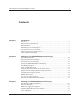
M™ Multi-touch Display M2256PW User Guide 3 Contents Chapter 1 Introduction Overview ....................................................................................................................5 Important Safety Information .....................................................................................5 Important Notes ..........................................................................................................7 Maintaining Your Touch Display .................................
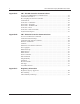
3M™ Multi-touch Display M2256PW User Guide Appendix A 3M™ PX USB Controller Communications Overview of USB Firmware Communications ........................................................21 Communication Basics .............................................................................................21 Receiving Reports from the Controller ....................................................................22 Command Set ...............................................................................
3M™ Multi-touch Display M2256PW User Guide 5 CHAPTER 1 Introduction Overview Congratulations on the purchase of your 3M™ Multi-touch Display M2256PW. This guide describes how to set up your M2256PW Multi-touch Display. The M2256PW Multi-touch Display is a 22” LCD with 16:10 aspect ratio with an attached desktop stand.
3M™ Multi-touch Display M2256PW User Guide Explanation of Signal Word Consequences DANGER: Indicates a potentially hazardous situation, which, if not avoided, will result in death or serious injury and/or property damage. WARNING: Indicates a potentially hazardous situation, which, if not avoided, could result in death or serious injury and/or property damage. CAUTION: Indicates a potentially hazardous situation, which, if not avoided, may result in minor or moderate injury and/or property damage.
3M™ Multi-touch Display M2256PW User Guide 7 CAUTION To avoid the potentially hazardous situations associated with the use of isopropyl alcohol which may result in minor or moderate injury or property damage: Follow all instructions and recommendations in the manufacturer's Material Safety Data Sheet and product label.
3M™ Multi-touch Display M2256PW User Guide • Do not install the display in a place where ventilation may be hindered. Always maintain adequate ventilation to protect the display from overheating and to promote reliable and continued operation. Touch Sensor Care and Cleaning The touch sensor requires very little maintenance. 3M Touch Systems recommends that you periodically clean the glass touch sensor surface. Be sure to turn off your display before cleaning.
3M™ Multi-touch Display M2256PW User Guide You can contact 3M Touch Systems, Inc. Technical Support (US only -- Eastern Standard Time) by calling the hot line, sending email or a fax. • • • • Technical Support Hot Line: 978-659-9200 Technical Support Fax: 978-659-9400 Toll Free: 1-866-407-6666 (Option 3) Email: US-TS-techsupport@mmm.com Contact 3M Touch Systems Contact information for all offices can be found on our website at: http://www.3m.com/touch 3M Touch Systems, Inc.
3M™ Multi-touch Display M2256PW User Guide CHAPTER 2 Setting up Your M2256PW Multi-touch Display This chapter describes how to set up your 3M Touch Systems M2256PW Multi-touch Display. You need to complete the following tasks: • • • • Unpack the components Connect the video, touch display cables, and power cables Power on the display and test your setup If you are not running Windows 7 (or Tablet PC), install MT7 software from the enclosed CD.
3M™ Multi-touch Display M2256PW User Guide 11 Unpacking Your Touch Display Carefully unpack the carton and inspect the contents.
3M™ Multi-touch Display M2256PW User Guide Connecting the Touch Display CAUTION You are cautioned that any change or modification to the equipment not expressly approved by the party responsible for compliance could void your authority to operate such equipment. To connect the M2256PW Multi-touch Display: 1. Turn off your computer. You should always turn off the computer before connecting or disconnecting a device. 2. Select either the DVI or VGA cable.
3M™ Multi-touch Display M2256PW User Guide 13 Video Card Requirements Before you connect your touch display, make sure your computer has a video card installed that supports the native video resolution of 1680 x 1050 for the M2256PW Multi-touch Display. If you need information on installing a video card or video driver, refer to the manual that came with your video card.
3M™ Multi-touch Display M2256PW User Guide Configuring the Display Settings After you connect your M2256PW Multi-touch Display and turn on your computer, you may need to configure one or more of these display settings.
3M™ Multi-touch Display M2256PW User Guide 15 Adjusting the M2256PW Video Display Your M2256PW Multi-touch Display has four controls to adjust the video display. • Menu – Shows or hides the on screen display menu. • Select -- Highlights the current menu option or saves the current setting. Press Ÿ or ź to change the value. • Ÿ/Up -- Enables you to scroll forward through items on the menu -- increase the value of selected option or move to the next menu item.
OSD 3M™ Multi-touch Display M2256PW User Guide Choices Description setting. CONTRAST Selecting the Contrast option increases or decreases the strength (lightness or dimness) of the image. Adjust the contrast using the up and down buttons and press SELECT to confirm the new setting. AUDIO Adjust the volume of the speakers COLOR Submenu Choices are User Defined Color, Preset Color Temperature, or Exit USER DEFINED COLOR Adjust the Red, Green and Blue channels to your preference.
3M™ Multi-touch Display M2256PW User Guide OSD Choices 17 Description TOOLS Choices are OSD Timing, OSD Horizontal, OSD Vertical OSD TIMING Adjust how long the menu remains on the screen. Submenu choices are: Recall, Sharpness, or Exit OSD HORIZONTAL and VERTICAL Adjusts the position of the OSD on your screen RECALL Resets the control functions back to the original factory preset values. In order for the Recall function to work, the timing must fall under one of the factory preset timing modes.
3M™ Multi-touch Display M2256PW User Guide CHAPTER 3 Enabling Your M2256PW Multi-touch Display Windows™ 7 USB Compatibility 3M multi-touch technology works seamlessly with the Windows™ 7 operating system. The Multi-touch display supports USB HID for direct communication. The M2256PW Multi-touch Display leverages all the multi-touch functionality that is native to Windows™ 7. Plug the display in to a system running Windows™ 7 and you’ll quickly enter the world of true multi-touch functionality.
3M™ Multi-touch Display M2256PW User Guide 19 Installing 3M™ MicroTouch™ Software Remember that Windows™ 7 does not require any additional software to enable multitouch functionality. However, for Windows™ XP, Vista or Linux® operating systems, 3M™ MicroTouch™ Software enables your M2256PW Multi-touch Display to work with your computer. 3M™ MicroTouch™ Software includes a control panel for setting your touch sensor preferences and a diagnostic utility.
3M™ Multi-touch Display M2256PW User Guide If you are using 3M™ MicroTouch™ MT 7 Software, launch the MT 7 Control Panel and follow the instructions on the Main tab. You'll be asked to touch 3 targets. If you are writing your own drivers, you should provide your own video alignment tool. Use the Paint program (Start> Programs> Accessories> Paint) to determine if you have multitouch operation. Retest the accuracy after you perform a calibration. 3M Touch Systems, Inc.
3M™ Multi-touch Display M2256PW User Guide 21 APPENDIX A 3M™ PX USB Controller Communications This appendix is intended for software developers only and discusses the fundamentals of communicating with the PX controller. The firmware commands, which are usually issued by a driver or utility program on the host system, control the operation of the controller. This appendix lists the recommended firmware commands and describes how to use each of these commands.
3M™ Multi-touch Display M2256PW User Guide synchronous report in response to some of these requests. You need to know product ID (0502H) and the vendor ID (0596H) to write your own driver. These values are required for identifying the controller. Receiving Reports from the Controller The controller sends a variety of reports to the computer. The first byte of each report is the Report ID that defines the structure and content of the report.
3M™ Multi-touch Display M2256PW User Guide 23 Table 2. Calibration Setup Stage Offset 0 1 2 Field bmRequestType bRequest wValue Size 1 1 2 Value 0x21 0x09 0x0303 4 6 wIndex wLength 2 2 0 8 Description Class,H2D,Interface Set Report Msb 03 = Feature Lsb 03 = Feature Report ID Always 0 Always 8 Table 3.
3M™ Multi-touch Display M2256PW User Guide The Calibrate Extended command then positions the first calibration target inward from the lower left corner (0,1049) and the second calibration target inward from the upper right corner (1679,0). The following illustration shows how the calibration targets are calculated for a Windows-based system. Your operating system may be different. The illustration below shows the coordinates of the calibration targets and display corners.
3M™ Multi-touch Display M2256PW User Guide 25 POC Status – The status of the Power-on Checks. Various controller systems are checked at power-up. If any failures in these systems are detected, a POC flag is set. The POC status field reports the state of these flags. Table 7.
3M™ Multi-touch Display M2256PW User Guide Table 10. Data Stage (controller response) Offset 0 1 Field Report ID Max Count Size 1 1 Value 0x12 0x1E Description Feature Report ID Number of actual 30 fingers supported Note: The number of actual contacts reported may exceed this number (possibly up to 60). Set Feature - Reset This is a request to perform a controller reset. Soft resets are automatic after any block parameter changes. Table 11.
3M™ Multi-touch Display M2256PW User Guide 27 Set Feature –Restore Defaults This is a request to restore parameter defaults. Table 13. Restore Defaults -- Setup Stage Offset 0 1 2 Field bmRequestType bRequest wValue Size 1 1 2 Value 0x21 0x09 0x0303 4 6 wIndex wLength 2 2 0 8 Description Class,H2D,Interface Set Report msb=03=Feature lsb=03= Feature Report ID Always 0 Always 8 Size 1 1 6 Value 0x03 0x08 0 Description Feature Report ID Restore Defaults Not used Table 14.
3M™ Multi-touch Display M2256PW User Guide Table 15.
3M™ Multi-touch Display M2256PW User Guide 29 APPENDIX B 3M™ PX Serial Controller Communications This appendix is intended for software developers only and discusses the fundamentals of communicating with the 3M™ PX serial controller. The firmware commands, which are usually issued by a driver or utility program on the host system, control the operation of the controller; however developers can enter these commands directly. This appendix: • • • • Describes the controller default settings.
3M™ Multi-touch Display M2256PW User Guide Controller Default Settings Communication Parameters The operation of the PX serial controllers is N81 (no parity, 8 data bits, and 1 stop bits) at 115,200 baud (nonadjustable). Data Format Data format refers to the type of packet the controller uses to send the X/Y touch coordinates to the host system. Format Tablet Multitouch is the default format for the 3M™ PX serial controller.
3M™ Multi-touch Display M2256PW User Guide 31 Sending Commands to the Controller When you send a command to the controller, you must use the correct command format. The general format of a command is as follows: Command Note: The following descriptions of header, command, and terminator, use 3M Touch Systems terminal emulator key sequences. You may need to enter the sequence in a different format, depending on your emulator.
3M™ Multi-touch Display M2256PW User Guide The command response, which always follows the header, is a range of ASCII characters depending on the type of command sent. Responses can be in many forms. For example, one standard response is 0 (ASCII character ‘zero’ or 30 hexadecimal). This response indicates a successful command completion for most commands, while it indicates a failed completion for other commands.
3M™ Multi-touch Display M2256PW User Guide 33 Note: When you enter commands in terminal mode, precede each command with A to enter the start of header. Table 17. Firmware Commands for PX Serial Controller Development Command Calibrate Get Copyright Mode Down Up Mode Inactive Mode Stream Name Null Command Output Identity Reset Restore Defaults Unit Type Code CX Q101 MDU MI MS NM Z OI R RD UT Description Initiates an interactive 2-point calibration. Returns the copyright string.
3M™ Multi-touch Display M2256PW User Guide Calibrate Procedure To use the CX command: 1. Enter the Calibrate (CX) command. The controller sends an initial acknowledgment of 0. 2. Touch the sensor at a lower left target, which is located 12.5% (1/8) in from the corner of the video image. The controller returns an acknowledgment of 1. This is a positive response.
3M™ Multi-touch Display M2256PW User Guide 35 The illustration below shows the coordinates of the calibration targets and display corners. The corners show the video coordinates in parentheses and the touch screen coordinates in brackets. Note that the touch screen coordinates for the serial interface have their origin in the lower-left corner.
Description: 3M™ Multi-touch Display M2256PW User Guide This is the default mode of operation at power up. Touch reports include touchdown and liftoff events as well as continuing touches. Name Command Syntax: NM Response: 0 Positive response. Description: Returns a name string Null Command Syntax: Z Response: 0 Positive response. Description: Queries the controller and waits for a response.
3M™ Multi-touch Display M2256PW User Guide 37 3M Touch Systems recommends that the host system issue a Reset command whenever the host system is powered on and is attempting to establish communication with the controller. The amount of time needed to execute a Reset command is typically 500 milliseconds with a defined maximum of 2000 milliseconds.
3M™ Multi-touch Display M2256PW User Guide AD Ffff = Four ASCII characters that indicate the features supported by the controller. **** Ss Indicates the PX series of controllers Indicates no additional features configured = Two ASCII characters that provide status information about the controller hardware. The two characters represent one byte. Each character is in the range 0 to 9 and A to F. Table 2 defines the meaning of each bit in the status byte.
3M™ Multi-touch Display M2256PW User Guide Data Sequence Bits Y - Byte 5 ID – Byte 6 7 0 0 39 6 Y13 N6 5 Y12 N5 4 Y11 N4 3 Y10 N3 2 Y9 N2 1 Y8 N1 0 Y7 N0 Note 1: P is the proximity bit. It is set to 1 when there is a touch, 0 for a liftoff. The ID is associated with a touch stream from one finger. The ID, in the range of 0-127, is assigned on a rotating basis at touchdown. A finger touch stream consists of a touchdown, maybe some continuing touch points, ending with a liftoff.
3M™ Multi-touch Display M2256PW User Guide APPENDIX C Regulatory Information Regulatory Agency Approvals Your product complies with the following regulatory standards: • FCC-B • CE • UL60950/IEC60950/EN60950 certified in compliance with the CB test scheme • RoHS/WEEE directives This equipment has been tested and found to comply within limits for a Class B digital device, pursuant to Part 15 of the FCC rules.
3M™ Multi-touch Display M2256PW User Guide 41 CAUTION You are cautioned that any change or modification to the equipment not expressly approved by the party responsible for compliance could void your authority to operate such equipment. This Class B digital apparatus meets all requirements of the Canadian InterferenceCausing Equipment Regulations. Cet appareil numérique de la classe B respecte toutes les exigences du Règlement sur le matériel brouilleur du Canada.