M150 Flat Panel Display Touch Monitor User Guide 3M Touch Systems Read and understand all safety information contained in this document before using this product.
M150 FPD Monitor Installation Guide The information in this document is subject to change without notice. No part of this document may be reproduced or transmitted in any form or by any means, electronic or mechanical, for any purpose, without the express written permission of 3M Touch Systems. 3M may have patents or pending patent applications, trademarks, copyrights, or other intellectual property rights covering subject matter in this document.
Contents Overview Important Safety Information ....................................................................................5 Intended Use ....................................................................................................... 5 Explanation of Symbols...................................................................................... 6 Service and Repair Indicators....................................................................................
M150 FPD Monitor Installation Guide Chapter 3 Video Display Options Adjusting the M150 Video Display.........................................................................23 Auto Config ...................................................................................................... 24 Brightness ......................................................................................................... 24 Contrast.....................................................................................
Overview Welcome to the world of 3M Touch Systems — a world where using a computer is as simple as touching the screen. This guide describes how to set up your M150 Flat Panel Display (FPD) touch monitor. This document assumes you have basic computer skills. You should know how to use the mouse and keyboard, choose commands from menus, open and run application programs, and save files. Important Safety Information Read and understand all safety information before using this product.
M150 FPD Monitor Installation Guide CAUTION To avoid the risk of electric shock which may result in minor or moderate injury: The socket-outlet should be installed near the equipment and should be easily accessible. Use a power cable that is properly grounded. Always use the appropriate AC cord certified for the individual country. Some examples are listed below: USA UL Switzerland SEV Canada CSA Britain BASE/BS Germany VDE Japan Electric Appliance Control Act Do not service the Flat Panel Display.
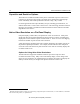
Overview 7 • To avoid ergonomic concerns: Do not install the monitor in a manner or location with awkward accessibility. Extended use may result in muscle, tendon, or fixed posture strains. It is recommended you take periodic breaks from continuous use. Service and Repair Indicators Do not attempt to service this unit yourself. Removing the display cover may expose you to dangerous voltage or other risks and will void the warranty.
M150 FPD Monitor Installation Guide • • • • Technical Support Hot Line: 978-659-9200 Technical Support Fax: 978-659-9400 Toll Free: 1-866-407-6666 Email: US-TS-techsupport@mmm.com 3M Touch Systems Worldwide Offices All offices can be reached through the website: http://www.3mtouch.com/.
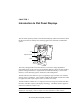
CHAPTER 1 Introduction to Flat Panel Displays The 3M Touch Systems product line of Flat Panel Display (FPD) touch monitors offers the M150 monitor for desktop and countertop applications with built-in multimedia options.
M150 FPD Monitor Installation Guide Capacitive and Resistive Options The monitor is available with 3M Touch System’s ClearTek® capacitive touch screen. Capacitive is the touch screen of choice for public access applications requiring high levels of durability and reliable performance 24 hours a day, 7 days a week. For those applications that require flexibility of input, including gloved hand use, we offer the M150 with a 5-wire resistive touch screen.
CHAPTER 2 Setting Up Your M150 FPD Monitor This chapter describes how to set up and integrate your 3M Touch Systems M150 FPD monitor into a touch application. You need to complete the following tasks: • Unpack the components • Connect the video, touch screen, and power cables • Power on the monitor and test your setup • Install the touch screen software • Calibrate the touch screen System Requirements The M150 flat panel touch monitor requires a personal computer (PC).
M150 FPD Monitor Installation Guide Unpacking Your Touch Monitor Carefully unpack the carton and inspect the contents.
Chapter 2 Setting Up Your M150 FPD Monitor 13 Figure 1 Disassembling the Yoke & Base for Arm Mounting Step 1 -- Unlock the yoke. With the unit laying face down safely and securely on a nonabrasive surface, remove the two screws connecting the top of the yoke. Lift yoke and pull down to disengage tabs to remove. Step 2 -- Remove the bottom two screws holding the hinge cover in place. Remove the small hinge cover.
M150 FPD Monitor Installation Guide Access to the Video Controls The controls for adjusting the video display are located on the front of the M150 FPD monitor. These buttons let you display the on-screen menu and adjust the phase, image position, contrast, and brightness. Make sure you have unobstructed access to the video controls once the M150 monitor is installed.
Chapter 2 Setting Up Your M150 FPD Monitor 15 Note: When the adjustment knob is horizontal it is locked; when it is in the vertical position it is unlocked. Always maintain adequate ventilation to protect the display from overheating and to ensure reliable and continued operation. Installing the Video Card and Video Driver Before you can connect your touch monitor, make sure your computer has a video card and driver already installed for the monitor.
M150 FPD Monitor Installation Guide Using the Standard Controls for the Video Card In addition to the standard controls on the monitor, each video card has several controls that let you adjust the display settings. The software and driver for each video card is unique. In most cases, you adjust these settings by using a program or utility provided by the manufacturer of the video card.
Chapter 2 Setting Up Your M150 FPD Monitor 17 ID Tech all MiniMag™ readers IDT 3331-02U IDT 3331-12U IDT 3331-23U IDT 3331-33U IDT 3321-02 IDT 3321-02PP IDT 3321-12 IDT 3321-12PP IDT 3321-23 IDT 3321-23PP MagTek all "mini" sized readers 2180201 2180202 2180203 2180204 2180205 2180206 21040103 21040104 IDT 3321-33 IDT 3321-33PP IDT 3331-02 IDT 3331-12 IDT 3331-23 IDT 3331-33 IDT3301-02 IDT3301-12 IDT3301-23 IDT3301-33 Figure 6 Card Reader Mounting and Cable Management 65-2305 Connecting the Touch Moni
M150 FPD Monitor Installation Guide 4. Plug the AC/DC power supply into the M150 FPD. Be sure to use the power supply included with the monitor. Figure 7 Identifying Your Monitor Connections Touch Screen Microphone out Line In Power Video Connection WARNING To avoid the risk of electric shock which could result in serious injury or death: This device must be operated with the original power supply, part number: HJC, HASU05F or CHI, CH-1234.
Chapter 2 Setting Up Your M150 FPD Monitor 19 Route all wiring and cabling away from heat sources and sharp metal edges to avoid damage. Also, keep the touch screen cable away from sources of electromagnetic and radio frequency interference. WARNING To avoid the risk of electric shock which could result in serious injury or death: • Do not use a damaged power supply. • Do not use a power cord that is frayed or otherwise damaged.
M150 FPD Monitor Installation Guide Testing the M150 FPD Note: The M150 FPD has a power status light located on the front of the bezel. After connection, turn on the power switch located at the bottom of the front bezel. Before you test your touch monitor, make sure all cables are connected properly and routed through the cable management system. Be sure to tighten all cable screws. To test that the monitor is working properly: 1. Turn on your computer. 2. Make sure the video image is displayed.
Chapter 2 Setting Up Your M150 FPD Monitor 21 Calibrating the Touch Screen After you connect your touch monitor and install TouchWare software, you must calibrate the touch screen. Calibration serves two purposes: • Sets the active area of the touch screen • Aligns the touch screen’s active area to the underlying video To calibrate the touch screen, open the touch screen control panel and select Calibrate. Follow the directions displayed on the screen.
CHAPTER 3 Video Display Options This chapter provides guidelines for adjusting the video display and using the monitor controls to adjust the image to your liking. Before you make any adjustments: • Be sure to adjust the controls in your normal lighting conditions. • Display a test image or pattern whenever you adjust the video. Adjusting the M150 Video Display Your M150 FPD monitor has four controls to adjust the video display. • MENU – Shows or hides the menu.
M150 FPD Monitor Installation Guide Auto Config To perform an Auto Config, press the ◄/left arrow key once then press SELECT. The Main Menu item Auto Config is used to adjust the configuration of the phase clock vertical and horizontal position automatically. A confirmation box is displayed to confirm the user selection. The default selection in the box is NO and is highlighted by a red bar. If the Select key is pressed, the main menu is redisplayed and nothing is changed.
Chapter 3 Video Display Options 25 Contrast Selecting the Contrast option will allow you to adjust the contrast of the display. Adjust the contrast using the ◄/left and ►/right arrow buttons, and press SELECT to confirm the new setting. Color When you choose the Color option from the OSD, this will bring up a sub-menu that allows you to adjust the RGB or Black Level color balance for your display. Use the ◄/left and ►/right arrow buttons to scroll through the color menu.
M150 FPD Monitor Installation Guide You can use the Position option to center the image on the display manually. Use the ◄/left and ►/right arrow buttons to scroll through the position menu. • H-Position is used to adjust the horizontal image position manually. • V-Position is used to adjust the vertical image position manually. Image Use the ◄/left and ►/right arrow buttons to scroll through the image menu.
Chapter 3 Video Display Options 27 Miscellaneous Menu The Miscellaneous Menu contains three options: Reset, OSD Position, and System info. • Reset is used to reload all factory default parameters. • OSD position is used to setup the OSD menu position – horizontal and vertical position is adjusted separately. Each position item will bring up the slider window – the maximum value of the sliders are based on the size of the OSD menu.
CHAPTER 4 Maintenance and Troubleshooting If you have a problem setting up or using your monitor, you may be able to solve it yourself. Before calling 3M Touch Systems, try the suggested actions that are appropriate to the problems you are experiencing with the monitor. You may also want to consult your video card user’s manual for additional troubleshooting advice.
M150 FPD Monitor Installation Guide • Apply the cleaner with a soft, lint-free cloth. Avoid using gritty cloths. • Always dampen the cloth and then clean the screen. Be sure to spray the cleaning liquid onto the cloth, not the screen, so that drips do not seep inside the display or stain the bezel. • Always handle the touch screen with care. Do not pull on or stress cables.
Chapter 4 Maintenance and Troubleshooting 31 Troubleshooting the Touch Screen If you are experiencing problems with the touch screen, check the following list of common installation errors. Table 2.
M150 FPD Monitor Installation Guide This equipment has been tested and found to comply within limits for a Class B digital device, pursuant to Part 15 of the FCC rules. These limits are designed to provide reasonable protection against harmful interference in residential installations. This equipment generates, uses and can radiate radio frequency energy, and if not installed and used in accordance with the instructions, may case harmful interference to radio communications.
Rear Edge of Base Not Shown M150 Base Plate Mounting Template Cut Line (Drawn actual size) 3M Touch Systems Proprietary Information Place this template on mounting surface and drill three holes as shown for mounting screws. The screw heads must be smaller than 0.39" (10 mm) and larger than 0.21" (5.5 mm). Adjust height of screw heads to securely lock monitor in place. This height is about 0.23" (6 mm). Drill 3 Mounting Holes 0.39" (10 mm) 0.21" (5.