MP8640 Multimedia Projector Operator's Guide MP8640 Projecteur multimédia Guide de l'opérateur MP8640 Multimedia-Projektor Benutzerhandbuch Proyector de Multimedia MP8640 Manual del Usuario MP8640 Proiettore Multimediale Manuale dell'operatore MP8640 Bruksanvisning for multimediaprojektor MP8640 Multimedia Projector Gebruiksaanwijzing © 3M 1997 3M™ Multimedia Projector MP8640
Table of Contents Safeguards ................................................................................................................. 3 Warranty ................................................................................................................. 4 Section 1: Unpack ....................................................................................................... 5 1.1 1.2 1.3 1.4 Section 2: 2.1 2.2 2.3 2.4 Section 3: 3.1 3.2 3.3 Section 4: 4.1 4.2 4.3 4.4 4.5 4.
Safeguards INTENDED USE Before operating the machine, please read the entire manual thoroughly. The 3M™ Multimedia Projector 8640 was designed, built and tested for use indoors, using 3M™ brand lamps and nominal local voltages. The use of other replacement lamps, outdoor operation or different voltages has not been tested and could damage the projector or peripheral equipment and/or create a potentially unsafe operating condition. IMPORTANT SAFEGUARDS 1. Read and understand all instructions before using.
Warranty THANK YOU FOR CHOOSING 3M Thank you for choosing 3M Multimedia Projector equipment. This product has been produced in accordance with 3M's highest quality and safety standards to ensure smooth and trouble free use in the years to come. For optimum performance, please follow the operating instructions carefully. We hope you will enjoy using this high performance product in your meetings, presentations and training sessions.
Section 1: Unpack 1.1 Contents of Shipping Box The 3M™ MP8640 Multimedia Projector is shipped with the necessary cables required for standard VCR, PC, MAC™ II or laptop computer connections. Carefully unpack and verify that you have all of the items shown below in Figure 1.1.
Section 2: Product Description 2.1 Machine Characteristics The MP8640 Multimedia Projector integrates metal halide lamp and polysilicon LCD display technology into a single unit. It accepts input from two different computer sources and two video/audio sources and projects a bright, super crisp image. Switching your presentation from a computer input to a video input, and then back to a computer input simply requires the push of a button on the remote control keypad or control panel keypad.
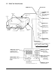
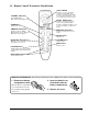
2.2 Main Unit Identification LAMP indicator ON indicator STANDBY / ON button Speakers Power ON/OFF button. OFF sets the unit in standby mode. Remote control sensor Handle TEMP Indicator MUTE button. ZOOM button Adjusts picture size. Cooling fan (exhaust) Lens Lens shutter Remote control sensor Cooling fan (inside) FOCUS button Adjusts focus. MENU button RESET button Resets unit to factory settings. INPUT button To select the input source.
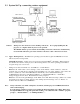
2.3 System Set Up - connecting various equipment AC In Socket VCR with S-VHS out Laptop Computer Desktop Computer VCR or Laser Disc Caution: Turn power off to all devices before making connections. projector or computer while any device is in operation. Never plug anything into the The MP8640 must be powered down when making connections. The mouse emulation may not work if the unit is not powered down before the mouse cable connections are made. 2.3.
2.4 Remote Control Transmitter Identification STICK SWITCH If Menu is on screen, stick switch controls movement within menu. If Menu is not displayed, stick switch is used for mouse emulation, i.e. left mouse button and cursor movement. STANDBY / ON button Power ON/OFF button. OFF sets the unit in standby mode. RESET / RIGHT button If Menu is on screen, button resets menu to factory default settings. If Menu is not displayed, button is used for mouse emulation, i.e. right mouse button.
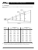
Section 3: Basic Operations 3.1 Installation Example of the Multimedia projector and screen installation. Determine picture size and projection distance as illustrated below. Maximum Zoom Minimum Zoom 178" 107" 72" 36" 24" 48" 71" 119" DISTANCE Distance To Screen Minimum Image Diagonal Width Height Maximum Image Diagonal Width Height 227 cm (7.4 ft) 102 cm (40 in.) 81 cm (32 in.) 61 cm (24 in.) 153 cm (60 in.) 122 cm (48 in.) 92 cm (36 in.) 341 cm (11.2 ft) 152 cm (60 in.) 121 cm (48 in.
3.2 Using the Projector 3 7 4 5 2 4 5 1 7 2 Note: Make all cable connections and line hookups FIRST. 1 Turn the MAIN POWER switch of the projector on. • The ON indicator will light up orange. 2 Open the lens shutter. • Push down lens shutter switch to open. 3 Press the STANDBY/ON button. • The ON indicator blinks (green) and then lights (green). • The ON indicator will blink green during warm-up and lamp ignition. 4 5 Adjust the screen size using the ZOOM button.
3.3 Turn Off the Power 1 1 2 3 1 Hold the STANDBY/ON button for 3-5 seconds. • The ON indicator blinks orange and the lamp turns off. After approximately 1 minute, the fan stops and the indicator stays orange. 2 Turn the MAIN POWER switch of the projector off. Caution: 3 Do not turn off the MAIN POWER switch before pressing the STANDBY/ON button. After the STANDBY/ON button is pressed, the fan rotates for about 1 minute to cool the projector. Close the lens shutter.
Section 4: Adjustment and Functions 4.1 Menu 1, 2 1 1 U EN M 2 T SE E R 1 Press the MENU ( ) buttons on projector or remote control MENU button. • On-screen menus are displayed on the screen. 2 Select the menu to be adjusted using the MENU ( STICK SWITCH. ) buttons or • Selected Menu is highlighted. 3 Select the item to be adjusted using the MENU ( or STICK SWITCH. ) buttons • Highlighted items may be adjusted.
4.2 How To Use Foot Adjusters Adjust the projection position using the foot adjusters at the bottom of the projector. Front view unlock ← → lock Foot adjusters Side view 4.2.1 4.2.2 4.2.3 Lift up the projector, unlock the foot adjusters. Adjust a viewing angle, and then lock the foot adjusters. For fine adjustments, rotate the foot adjusters. Caution: Do not unlock the foot adjusters if the projector is not supported.
4.3 SETUP The menu SETUP is used to adjust the image and to move the image position. RGB signal input Video signal input Adjustment Item VOLUME Decrease BRIGHT (BRIGHTNESS) © 3M 1997 Increase Dark Bright Lower Higher SHARPNESS Soft Sharp COLOR Less More TINT Red Green CONTRAST Note: Details of adjustment V.POSIT (V.POSITION) Moves the picture up or down. H.POSIT (H.POSITION) Moves the picture left or right. H.PHASE Decreases the picture flicker H.
4.4 INPUT The menu INPUT is used to select the input source. SETUP INPUT IMAGE OPT. RGB1 RGB2 VIDEO1 VIDEO2 TEST PATTERN Selection Description RGB1 Selects the RGB 1 terminal. RGB2 Selects the RGB 2 terminal. VIDEO1 Selects the VIDEO 1 terminal. VIDEO2 Selects the VIDEO 2 terminal. TEST PATTERN Selects the TEST PATTERN. (Start up screen). SYSTEM Selects the video signal format. 4.5 IMAGE The IMAGE menu is used to alter the image. SETUP INPUT IMAGE OPT.
4.5 IMAGE (continued) SETUP INPUT MESSAGE Selection © 3M 1997 OPT. TURN ON TURN OFF Description MIRROR Inverts the picture horizontally or vertically. H : INVERT Inverts the picture horizontally. V : INTERT Inverts the picture vertically. H&V : INVERT Inverts the picture horizontally and vertically. BLANK Selects the blank color. REVEAL Selects reveal speed. Note: For XGA inputs, "REVEAL" does not work. DISP. SIZE See chart below. MESSAGE Turn off the on-screen message.
4.6 OPT The OPT. menu allows you to control communication function. SETUP INPUT IMAGE OPT. COM. SPEED COM. BITS TIMER LANGUAGE AUTO OFF STARTUP SETUP SETUP INPUT IMAGE OPT. COM. SPEED (bps) 1200 2400 4800 9600 19200 INPUT OPT. IMAGE SETUP INPUT SETUP INPUT SETUP 10 min. IMAGE AUTO OFF 7N1 8N1 INPUT IMAGE OPT. ENGLISH FRANCAIS DEUTSCH ESPANOL ITALIANO NORSK NEDERLANDS STARTUP OPT. TURN ON TURN OFF 0 min. STOP Selection Description COM.
Section 5: Connection to Signal Terminals 5.1 Connection to the Video Signal Terminal a. Input signal S-VIDEO signal Luminance signal Chrominance signal VIDEO signal 1.0Vp-p, 75Ω termination AUDIO signal b. Signal input terminal 1.0Vp-p, 75 Ω termination 0.286Vp-p (burst signal), 75 Ω termination Input 200mVrms, 20 kΩ below (MAX 3.
c. Example of computer signal Interlaced / Non-interlaced Computer/Signal source Resolution H×V fH (kHz) fV (Hz) 15kHz RGB (NTSC) — 15.7 60 VGA-1 (IBM compatible) 640 × 350 31.5 70.1 H, V separate H: Positive V: Negative Non-interlaced Note: 3 VGA-2 (IBM compatible) 640 × 400 31.5 70.1 H, V separate H: Negative V: Positive Non-interlaced Note: 3 VGA-3 (IBM compatible) 640 × 480 31.5 59.
5.3 Connection to the Control Signal Terminal a. Mouse emulation (1) While the projector and computer are turned OFF, connect the projector and the mouse terminal of computer using an appropriate cable. (PS/2, Serial or ADB) (2) Turn ON the projector. (3) Turn ON the computer. (4) Select the correct mouse driver for the application. See computer's User Manual for this procedure.
5.3 Connection to the Control Signal Terminal (continued) Serial mouse (male) D-sub 15pin (Female) Serial Mouse cable b. RS 232 Control Cable (not included with basic packout) This cable is used to directly control the projector without using the Remote Control or Operator's Panel.
Section 6: Maintenance 6.1 Cleaning the Air Filter Note: Clean the air filter about every 50 hours. a) Turn off the MAIN POWER switch of the projector and pull out power cord. Let cool for 20 minutes. b) Remove the air filter from the bottom of projector. Unscrew two retaining screws and pull down and out on the handle to free air cleaner door. Carefully lift up and out on filter door. Remove the air filter c) Clean the air filter using a vacuum cleaner.
6.3 Lamp The following symptoms may indicate a lamp in need of replacement: • A dark picture. • LAMP indicator lights up red. • "CHANGE THE LAMP" message appears on the screen. Display Lamp Operation Hours If there is a need to determine the lamp operation hours, follow these steps: a) While the projector is running, press and hold the timer button on the remote control for 3 seconds. b) The operating time of the lamp will be displayed.
6.3.3 Remove lamp module: Grasp the lamp module with the one hand and the projector body opening with the other hand. Apply pressure to the projector body as you slide the lamp out. 6.3.4 Insert lamp module: Carefully insert the new lamp module. Ensure that it is fully seated. Tighten the lamp module retaining screws to secure the lamp module in place. Insert the hinge tabs on the left side of the lamp access door, then close and tighten the retaining screws to secure the door. 6.
Section 7: Technical Specifications 7.1 Specifications Note: All specifications are subject to change without notice. Product name Multimedia projector Model Name MP8640 Display system 3 beam poly-silicon LCD Liquid crystal panel Panel size 1.3 inches (33 mm) Drive system TFT active matrix Number of pixels 480,000 pixels (V600 × H800) per panel. 1.44 million pixels total with 3 panels. Lens F/Number: F/2.3 – F/3.
7.
Let us help you make the most of your next presentation. We offer everything from presentation supplies to tips for better meetings. And we're the only transparency manufacturer that offers a recycling program for your used transparencies. For late-breaking news, handy reference and free product samples, call us toll-free in the continental United States and Canada from 7:30 a.m. to 5:30 p.m. (CST) or visit our Internet Website. 3M Austin Center Building A145-5N-01 6801 River Place Blvd.