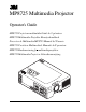
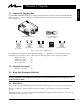
MP8725 Multimedia Projector Operator's Guide MP8725 Projecteur multimédia Guide de l'opérateur MP8725 Multimedia-Projektor Benutzerhandbuch Proyector de Multimedia MP8725 Manual del Usuario MP8725 Proiettore Multimediale Manuale dell'operatore MP8725 Bruksanvisning for multimediaprojektor MP8725 Multimedia Projector Gebruiksaanwijzing P M LA P M TE ET ES R U TE EN U M M ST O N Y/ B A N D IN PU T AC IN 1 RG AU 1 DIO B IN 2 AU D OU IO T IN CO NT 2 RO S-V L ID EO RG B IN VID
Safeguards ................................................................................................................. 1 Warranty ................................................................................................................. 2 Section 1: Unpack ....................................................................................................... 3 1.1 1.2 1.3 1.4 Section 2: 2.1 2.2 2.3 2.4 Section 3: 3.1 3.2 Section 4: 4.1 4.2 4.3 4.4 4.5 4.6 Section 5: 5.1 Section 6: 6.
Safeguards Before operating the machine, please read the entire manual thoroughly. The 3M™ Multimedia Projector 8725 was designed, built and tested for use indoors, using 3M™ brand lamps, 3M™ brand ceiling mount hardware and nominal local voltages. The use of other replacement lamps, outdoor operation, environments containing heavy cigarette smoke or different voltages have not been tested and could damage the projector or peripheral equipment and/or create a potentially unsafe operating condition.
ENGLISH Warranty LIMITED WARRANTY 3M warrants this product against any defects in material and workmanship, under normal usage and storage, for a period of two years from date of purchase. Proof of purchase date will be required with any warranty claim. In the event this product is found to be defective within the warranty period, 3M's only obligation and your exclusive remedy shall be replacement of any defective parts (labor included).
ENGLISH Section 1: Unpack 1.1 Contents of Shipping Box The 3M™ MP8725 Multimedia Projector is shipped with the necessary cables required for standard VCR, PC, MAC™ II or laptop computer connections. Carefully unpack and verify that you have all of the items shown below in Figure 1.1.
2.1 Machine Characteristics The MP8725 Multimedia Projector integrates ultra-high performance lamp and polysilicon LCD display technology into a single unit. It accepts input from two different computer sources and two video/audio sources and projects a bright, super crisp image. Switching your presentation from a computer input to a video input, and then back to a computer input simply requires the push of a button on the remote control keypad or control panel keypad.
2.
2.4 Remote Control Transmitter Identification ENGLISH MUTE button Press MUTE to switch the audio sound ON or OFF LASER APERTURE STANDBY / ON button VOLUME button Set main power switch to ON. Press and hold STANDBY/ON button for projector mode (lamp on) or standby mode (lamp off). Press +/- to adjust internal/external speaker volume. STANDBY/ON MUTE MAGNIFY buttons Press +/- to magnify image (4x magification). Press POSITION button and use disc pad to view entire image.
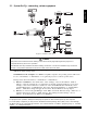
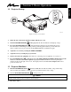
Section 3: Basic Operations ENGLISH 3.1 Projector Startup STANDBY/ON INPUT MUTE MENU MP MP TE LA RESET RE SE T ME MU NU TE ST AN DB Y/ON O I INPU T LAMP TEMP AC IN 1 RG AU 1 DIO B IN 2 AU D OU IO T IN CO NT 2 RO S- L VID EO RG B IN VID EO OU T AU DIO (L) IN MON O (R ) EPS-07A Figure 3.1 Projector Controls 1. Make all cable connections and line hookups with the power off. 2. Turn the POWER SWITCH 3. Press the STANDBY/ON button .
ENGLISH Section 4: Adjustment and Functions 4.1 Menu Navigation MENU EPS-20A Figure 4.1 Menu Button 1. Press any MENU button on projector or remote control MENU button. On-screen menus are displayed on the screen. 2. Select the menu to be adjusted using the MENU ( Selected Menu is highlighted. 3. Select the item to be adjusted using the MENU ( Highlighted items may be adjusted. ) buttons or DISC PAD. ) buttons or DISC PAD.
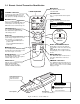
4.2 How To Use Height Adjustment Feet 1. Raise the front end of the projector so the foot is not touching the table top. 2. Push the lock button to unlock the foot. 3. Extend or retract the foot to the desired height. 4. Release the lock button to lock the foot into position. 5. For fine adjustments, rotate the foot. ENGLISH Adjust the image elevation using the height adjustment at the front of the projector. Caution Do not unlock the foot adjuster if the projector is not supported.
4.3 SETUP ENGLISH The SETUP sub-menu is used to adjust and move the image position. The projector will display either the RGB (Figure 4.4) or Video (Figure 4.5) menu according to the input source being projected. RGB signal input SETUP INPUT VOLUME BRIGHT CONTRAST V.POSIT H.POSIT H.PHASE H.SIZE COLOR BAL IMAGE Video signal input SETUP OPT. VOLUME BRIGHT (BRIGHTNESS) CONTRAST 121 AUTO 57 7 800 OPT. Figure 4.
4.4 INPUT SETUP INPUT RGB1 RGB2 VIDEO IMAGE OPT. SYSTEM AUTO NTSC PAL SECAM NTSC4 . 43 M-PAL N-PAL SETUP INPUT Value RGB1 Selects the RGB1 terminal RGB2 Selects the RGB2 terminal Video Selects the VIDEO terminal © 3M 1999 3M™ Multimedia Projector MP8725 OPT. RGB1 RGB2 VIDEO Figure 4.6 Input Menu Adjustment Area IMAGE ENGLISH The menu INPUT sub-menu (Figure 4.6) is used to select the input source. The VIDEO values (Figure 4.7) have additional values that can be selected. Figure 4.
4.5 IMAGE ENGLISH The IMAGE sub-menu is used to change the image characteristics. SETUP INPUT IMAGE OPT. MIRROR BLANK REVEAL MESSAGE SETUP INPUT MIRROR SETUP INPUT REVEAL IMAGE OPT. SETUP INPUT BLANK NORMAL H : INVERT V : INVERT H&V : INVERT IMAGE IMAGE OPT. SETUP INPUT WHITE BLUE BLACK IMAGE MESSAGE FAST OPT. OPT. TURN ON TURN OFF MEDIUM SLOW Figure 4.8 Image Adjustment Screens Adjustment Screen MIRROR Inverts the picture horizontally or vertically.
4.6 OPT SETUP INPUT IMAGE ENGLISH The OPT. sub-menu allows you to control communication function. OPT. COM. SPEED COM. BITS TIMER LANGUAGE AUTO OFF STARTUP SETUP SETUP INPUT IMAGE OPT. COM. SPEED (bps) 1200 2400 4800 9600 19200 INPUT OPT. IMAGE SETUP INPUT COM. BITS SETUP INPUT LANGUAGE TIMER SETUP INPUT 10 min. IMAGE AUTO OFF IMAGE OPT. SETUP INPUT STARTUP 0 min. STOP IMAGE OPT. 7N1 8N1 OPT. ENGLISH FRANCAIS DEUTSCH ESPANOL ITALIANO NORSK NEDERLANDS IMAGE OPT.
5.1 Cleaning the Air Filter ✔ Note Clean the air filter about every 50 hours, or when CHECK THE AIR FLOW is displayed. 1. Turn off the MAIN POWER switch of the projector and pull out power cord. Let cool for 20 minutes. 2. Press tab (2) to release air filter door. P M Power ET ES A N D B Y/O N M U TE IN PU T R M EN U LA TE M P 1 ST ENGLISH Section 5: Maintenance 2 3 EPS-09A Figure 5.1 Remove Air Filter 3. Carefully remove foam air filter screen (3) from air filter door. 4.
Section 6: Lamp ENGLISH 6.1 Lamp The following symptoms may indicate a lamp in need of replacement: • • LAMP indicator lights up red. "CHANGE THE LAMP" message appears on the screen. ✔ Note This lamp contains mercury. Consult your local hazardous waste regulations and dispose of this lamp in a proper manner. 6.2 Display Lamp Operation Hours To determine the lamp operation hours, follow these steps: 1. While the projector is running, press and hold the timer button on the remote control for 3 seconds. 2.
6.3 Replacing the Lamp ENGLISH WARNING To reduce the risk of electrical shock, always turn off projector and disconnect power cord before changing lamp. Caution To reduce the risk of severe burns, allow the projector to cool for at least 45 minutes before replacing the lamp. To reduce the risk of cuts to fingers and damage to internal components, use caution when removing lamp glass that has failed and shattered into sharp pieces.
Section 7: Troubleshooting 7.1 Sympton/Solution Table Cause Solution Power cannot be turned on. • The Main power is not turned on. • The power cord is disconnected. • 60 seconds have not elpsed since the power was turned off. No picture and sound • The setting of the input source is not • Set the correct input using the input select button of correct. the projector or the remote control • RGB/Video/Audio wiring to projector is • Connect the cable to correct input/output source. not correct.
ENGLISH Section 8: Accessories 8.1 Service Information For product information, product assistance, service information, or to order accessories, please call: In U.S. or Canada: 1-800-328-1371 In other locations, contact your local 3M Sales office. Accessories Part Number Ultra-high performance lamp module, 120 W . . . . . . . . . . . . . . . Power cord (US) . . . . . . . . . . . . . . . . . . . . . . . . . . . . . . . . . . . . . . Power cord (UK) . . . . . . . . . . . . . . . . . . . . . . . . . . . .
Technical Appendix Table of Contents A.1 A.2 A.3 A.4 A.5 A.6 A.7 Technical Specifications Dimensions Projector-to-Screen Distance Connection to the Video Signal Terminal Connection to the RGB Signal Terminal Indicator Status Connection to the Control Signal Terminal A.1 Technical Specifications ✔ Note All specifications are subject to change without notice. Product name Multimedia projector Model Name MP8725 Display system 3 LCD panels, RGB shutter system. Panel size 0.
A.2 Dimension TEMP O I LAMP AC IN RESET MENU MUTE INPUT STANDBY/ON AUDIO IN 1 2 AUDIO OUT 330 mm (13.2 in.) 336 mm (13.4 in.) 1 CONTROL RGB IN 2 RGB OUT S-VIDEO IN VIDEO (L) AUDIO IN (R) MONO 257.5 mm (10.3 in.) 106 mm (4.3 in.) TECHNICAL EPS-03A A.
A.3 Projector-to-Screen Distance Example of the Multimedia projector and screen installation. Determine picture size and projection distance as illustrated below. Maximum Zoom Minimum Zoom 178" 107" 72" 36" S-VIDEO IN O I 1 RGB IN 2 VIDEO CONTROL RGB OUT AUDIO IN (L) AC IN MONO AUDIO IN 1 2 AUDIO OUT (R) Distance Distance To Screen Minimum Image Diagonal Width Height Maximum Image Diagonal Width Height 214 cm (7.0 ft) 102 cm (40 in.) 81 cm (32 in.) 61 cm (24 in.) 130 cm (51 in.
A.4 Connection to the Video Signal Terminal a) Input signal S-VIDEO signal Luminance signal Chrominance signal VIDEO signal 1.0Vp-p, 75Ω termination AUDIO signal b) Signal input terminal 1.0Vp-p, 75 Ω termination 0.286Vp-p (burst signal), 75 Ω termination Input 200mVrms, 20 kΩ below (MAX 3.0Vp-p) Output 0~200mVrms, 1k Ω Chrominance signal Ground Luminance signal Ground S VIDEO input (Mini DIN4 pin) ✔ Note Video input signal terminals have priority in the following order: 1.
c) Example of computer signal Resolution HxV Refresh Rate Horizontal Frequency 640 x 350 70.1 Hz 640 x 400 Standard Type Note Display Dots HxV 31.5 kHz VGA-1 1024 x 560 56.4 Hz 24.8 kHz NEC PC9801 1024 x 640 640 x 400 70.1 Hz 31.5 kHz VGA-2 1024 x 640 640 x 480 85.0 Hz 43.3 kHz VESA 640 x 480 59.9 Hz 31.5 kHz VESA 640 x 480 66.7 Hz 35.0 kHz 640 x 480 72.8 Hz 37.9 kHz VESA 1024 x 768 640 x 480 75.0 Hz 37.5 kHz VESA 1024 x 768 800 x 600 56.3 Hz 35.
A.6 Indicator Status The ON, LAMP and TEMP indicators will light or blink in the following cases: Indicator status ON indicator Remedy Meaning Lights orange Standby mode normal Blinks green During warming up normal Lights green During operation normal Blinks orange During cooling down normal Lights red Lamp cannot light Cool projector by power off for 20 minutes. Blinks red Air filter open Ensure filter is closed. Lights red Temperature inside too high Let projector cool 20 minutes.
A.7 Connection to the Control Signal Terminal a) Mouse emulation (1) While the projector and computer are turned OFF, connect the projector and the mouse terminal of computer using an appropriate cable. (PS/2, Serial or ADB) (2) Turn ON the projector. (3) Turn ON the computer. (4) Select the correct mouse driver for the application. See computer's User Manual for this procedure.
A.7 Connection to the Control Signal Terminal (continued) Serial mouse Projector D-sub 15pin (Female) 1 5 6 SEL0 RTS 10 11 15 GND RDP TDP b) 1 2 3 4 5 6 7 8 9 10 11 12 13 14 15 1 2 3 4 5 6 7 8 9 Computer CD RD TD DTR GND DSR RTS DTS RI (male) D-sub 9pin 1 5 6 9 Serial Mouse cable RS-232 Control Cable (not included with basic packout) This cable is used to directly control the projector without using the Remote Control or Operator's Panel.
Serial Command Codes All numbers in this document are in Hexadecimal. You must send at the same communication setting as the projector and use a null modem serial cable to connect to the projector. There are four types of messages: 1) ASK, 2) REPLY, 3) SET and 4) DEFAULT. Ask Code: User: 20 XX XX is the attribute you are checking. Projector: 1Y XX Y bytes of data This is a reply code. The Y is the number of extra bytes that come after the command. The XX is the same as in the Ask code.
Serial Command Code Table Function Mouse Command Code 05 # Bytes 1 Communication 06 1 Power 11 1 Mirror 14 1 Magnify 15 Set Command 6 Data Code 00 01-7F 0X 1X X0 X1 X2 X3 X4 1E 1F 00 01 02 03 00 00 00 00 00 00 00 00-3C 05 00 00-0D 04 64 00-20 06 TECHNICAL Ask Commend 1 Freeze 16 1 Input 21 1 Video Type 22 2 Volume Mute 23 24 1 1 Brightness 31 3 Contrast 32 3 Color 33 3 Tint 34 3 Sharpness 35 3 A.
Serial Command Code Table (con't) Function H. Phase Command Code 37 # Bytes 3 H. Position 38 4 H. Size 36 4 V.
TECHNICAL A.
All statements, technical information, and recommendations related to Seller’s products are based on information believed to be reliable, but the accuracy or completeness thereof is not guaranteed. Before utilizing the product, the user should determine the suitability of the product for its intended use. The user assumes all risks and liability whatsoever in connection with such use.