MP8746/MP8747 Personal Projector Operator’s Guide MP8746/MP8747 Projecteur personnel Guide de l’opérateur MP8746/MP8747 Personal Projektor - Benutzerhandbuch MP8746/MP8747 Guía del usuario del proyector personal MP8746/MP8747 Guida dell’operatore per il Proiettore personale MP8746/MP8747 Bruksanvisning för Personlig projektor MP8746/MP8747 Personal Projector – gebruiksaanwijzing © 3M IPC 2000 3M™ Personal Projector MP8746/MP8747 1
(This page intentionally left blank for printed version.
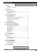
Table of Contents On the CD-ROM, please click on any section to jump to that section. Introduction Safeguards .................................................................................... 4 Thank You for Choosing 3M .......................................................... 6 Warranty ........................................................................................ 6 Section 1: Unpack Contents of Shipping Box ..............................................................
Introduction Intended Use Before operating the machine, please read this entire manual thoroughly. The 3M™ Personal Projector MP8746/MP8747 was designed, built, and tested for use indoors, using 3M lamps, 3M ceiling mount hardware, and nominal local voltages.
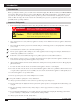
Introduction Location of Product Safety Labels The following safety labels are used on or within the MP8746/MP8747 projector to alert you to items or areas requiring your attention. CAUTION/VORSICHT/MESURE DE PRÉCAUTION/ATTENZIONE/PRECAUCIÓN Turning the knob too much makes it come off. / Der Verstellknopf löst sich wenn er überdreht wird. / Si vous manipulez excessivament la poignée, elle se detachera. / Se si gira troppo la manipola si stacca. / Grandola demasiado la manivela se desprende.
Introduction Thank You for Choosing 3M Thank you for choosing 3M multimedia projection equipment. This product has been produced in accordance with 3M’s highest quality and safety standards to ensure smooth and troublefree use in the years to come. For optimum performance, please follow the operating instructions carefully. We hope you will enjoy using this high performance product in your meetings, presentations, and training sessions.
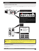
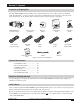
Section 1: Unpack Contents of Shipping Box The 3M™ MP8746/MP8747 Personal Projector is shipped with the necessary cables required for standard VCR, PC, Macintosh™ or laptop computer connections. Carefully unpack and verify that you have all of the items shown below. If any of these items are missing, please contact your place of purchase. P8747 MP8746/Mia Projector Multimed fety Guide Product Sa VIDEO STANDBY/ON LASER RGB BLANK MP8746/MP8747 Operator’s Guide You will need Adobe Acrobat version 4.
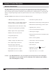
Section 2: Product Description Machine Characteristics The MP8746/MP8747 Personal Projector integrates ultra-high bright lamp and polysilicon LCD display technology into a single unit. It accepts input from two computer sources and two video/audio sources, and projects a bright, super-crisp image. Switching your presentation from a computer input to a video input, then back to a computer input simply requires the push of a button on the remote control keypad or control panel keypad.
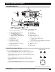
Section 2: Product Description Part Identification List 2 3 VIDEO STANDBY/ON LASER 1 RGB BLANK AUTO MENU POSITION 4 MENU SELECT RESET FREEZE VOLUME MAGNIFY OFF MUTE TIMER 13 19 6 14 17 12 16 10 11 9 7 15 AUDIO IN R AUDIO-1 VIDEO IN 5 8 1 S-VIDEO IN RGB IN 2 L 2 AUDIO-OUT USB RGB OUT CONTROL IN 18 Figure 2.1 Identifying MP8746/MP8747 Parts 1. Remote control transmitter 2.
Section 2: Product Description System Setup—Connecting to Various Equipment Power Cable AC Power Outlet RGB PC or Mac Cable Mouse Cable Desktop Computer Mac Adapter Mac Adapter (if needed) Audio (if needed) RGB Cable PC or Mac Cable USB Cable or RGB Laptop Computer Cable Audio Cable VIDEO IN AUDIO IN R 1 S-VIDEO IN RGB IN 2 L AUDIO-1 2 AUDIO-OUT RGB OUT USB CONTROL RGB Cable S-VHS Cable Video Cables IN Audio USB Cables Cable Video Monitor Audio Cable VCR with Audio S
Section 2: Product Description System Setup—Connecting to Various Equipment (continued) Cable Connections RGB Signal input (video from computer) Connect one end of the enclosed RGB cable to the RGB IN 1 or 2 terminal of the projector. Connect the other end to the RGB signal output or RGB OUT of the computer. ✓ Note: For Macintosh computers, the optional Mac adapter is necessary. Please consult your dealer to order one, if necessary. Ordering information is on page 30. Figure 2.
Section 2: Product Description Remote Control Transmitter Identification Use the remote control transmitter within a distance of approximately 3 meters (or 9.8 feet) from the sensor of the front of the projector, and within a range of 30° to the left and right. Strong light and obstacles may interfere with operation of the remote control transmitter.
Section 2: Product Description Changing Remote Control Battery When remote control transmitter becomes difficult to operate or does not respond, it usually needs new batteries. 1. Turn over the remote control transmitter to access the battery holder. 2. Push the battery cover tab as indicated and lift up to remove it. 3. Lift old batteries out of compartment. 4. Replace with two AA batteries. Make sure the positive (+) and negative (-) terminals are correctly oriented. 5.
Section 2: Product Description Mouse Emulation (continued) The mouse type and cable type are determined by the type of computer used. Use the table shown below to select the appropriate cable or refer to your computer’s user manual. Connect as shown in the diagram.
Section 2: Product Description Remote Control Mouse Function (continued) For USB 1. Use the enclosed USB cable to connect the computer to the mouse unit. Turn on the computer power before or after connecting the USB cable. 2. When this mouse is connected for the first time, a message may appear on the screen concerning the installation of USB software. Follow the instructions on the screen and install suitable software. 3. If there are still problems, reconnect the cables. 4.
Section 3: Basic Operations Projector Start-up STANDBY/ON MUTE INPUT RESET Figure 3.1 Projector Controls 1. Make all equipment and cable connections with the power off. 2. Turn on the MAIN POWER SWITCH 3. Press the STANDBY/ON button . The ON indicator will blink green during warm-up and lamp ignition, then stay green to indicate correct operation. When power is turned off, there is a 60-second reset period before the STANDBY/ON button will function again. 4. Turn on all connected equipment.
Section 4: Adjustments and Functions How to Use Height Adjustment Foot Adjust the image elevation and projection angle (within 0 to 9°) using the height adjustment foot at the front of the projector and the tilt adjustment knob at the rear of the computer. 1. 2. 3. 4. 5. Raise the front end of the projector so the foot is not touching the tabletop. Push the lock button on the left side of the projector to unlock the foot. Extend or retract the foot to the desired height.
Section 4: Adjustments and Functions Plug & Play Function Plug & Play is a system configured with peripheral equipment (including a computer and display), and a compatible operating system. This allows the user to connect various peripheral equipment successfully without having to adjust settings manually. The equipment and projector exchange this information automatically. This projector is VESA DDC (Display Data Channel) 1/2B compatible.
Section 4: Adjustments and Functions Menu Navigation MENU POSITION MENU SELECT RESET Figure 4.3 Menu Disk button on projector and Menu buttons from basic remote control transmitter 1. Press MENU DISK button on projector or remote control MENU buttons. On-screen menus are displayed on the projected image. 2. Select the menu to be adjusted by pressing the right or left arrows on the MENU DISK buttons or the remote control. Selected Menu is then highlighted. 3.
Section 4: Adjustments and Functions SETUP Submenu The SETUP sub-menu is used to adjust and move the image position. The projector will display either the RGB (Figure 4.6) or Video (Figure 4.7) submenu, according to the input source being projected. SETUP INPUT IMAGE OPT. SETUP INPUT BRIGHT BRIGHT CONTRAST CONTRAST V POSIT SHARPNESS H POSIT 121 H PHASE 57 TINT H SIZE COLOR BAL R 800 COLOR BAL R OPT. COLOR 7 H SIZE IMAGE COLOR BAL B COLOR BAL B ASPECT Figure 4.
Section 4: Adjustments and Functions INPUT Submenu The INPUT submenu is used to select the RGB or video input source. The RGB values are shown in Figure 4.8. The Video values are shown in Figure 4.9. SETUP INPUT RGB IMAGE FH: 48.3 VIDEO FV: 60 OPT. SETUP KHz INPUT IMAGE OPT. RGB Hz AUTO VIDEO AUTO NTSC AUTO PAL SECAM NTSC4.43 M-PAL N-PAL Figure 4.8 RGB Input Submenu SETUP Figure 4.9 Video Input Submenu INPUT IMAGE OPT. RGB VIDEO AUTO EXECUTE CANCEL Figure 4.
Section 4: Adjustments and Functions IMAGE Submenu The IMAGE submenu is used to change the image characteristics. SETUP INPUT IMAGE KEYSTONE BLANK MIRROR START UP SETUP KEYSTONE BLANK MIRROR START UP OPT. ±0 INPUT IMAGE NORMAL H: INVERT V: INVERT H&V: INVERT OPT. SETUP INPUT IMAGE OPT. INPUT IMAGE OPT. KEYSTONE BLANK MIRROR START UP SETUP KEYSTONE BLANK MIRROR START UP TURN ON TURN OFF Figure 4.
Section 4: Adjustments and Functions OPT. Submenu The OPT. submenu allows you to control communication function. SETUP INPUT IMAGE OPT. SETUP 8 VOLUME MENU COLOR TIMER LANGUAGE AUTO OFF AUTO OFF SYNC ON G SYNC ON G IMAGE OPT. SETUP INPUT VOLUME VOLUME MENU COLOR MENU COLOR TIMER TIMER 15 min. LANGUAGE OPT. IMAGE OPT.
Section 5: Maintenance Cleaning the Air Filter ✔ Note: Clean the air filter about every 100 hours or if the message “CHECK AIR FLOW” is displayed on the screen. If air is restricted due to dust accumulation on filter, the projector may overheat and shut down automatically. Turn off the MAIN POWER SWITCH of the projector and pull out power cord. Let cool for 20 minutes. Vacuum dust and dirt from filter. If the filter cannot be cleaned and needs to be replaced, please consult your dealer. K Figure 5.
Section 6: Lamp Lamp The following symptoms may indicate that the lamp needs to be replaced: • LAMP indicator lights up red. • “CHANGE THE LAMP” message appears on the screen. Display Lamp Operation Hours To determine the lamp operation hours: 1. While the projector is running, press and hold the TIMER button on the remote control for three seconds. 2. The operating time of the lamp will be displayed at the bottom of the screen.
Section 6: Lamp Replacing the Lamp WARNING WARNING To reduce the risk of electrical shock, always turn off projector and disconnect power cord before changing lamp. ✔ Note: For maximum lamp life, do not shock, handle or scratch the lamp glass when it is hot. Do not use an old or previously used lamp as a replacement lamp. 1. Remove lamp access door: The lamp access door is located on the bottom of the machine. Use a flathead screwdriver to remove the two screws from the lamp access door.
Section 7: Troubleshooting Symptoms/Solutions Symptom Cause Solution Power cannot be turned on. • MAIN POWER switch is not turned on. • Turn the MAIN POWER switch on. • The power cord is disconnected. • Insert the power cord into an AC socket. • 60 seconds have not elapsed since • Wait 60 seconds before turning on power. the power was turned off. No picture or sound. • The setting of the input source is not • Set the correct input using the input select button of correct.
Section 7: Troubleshooting Messages/Solutions Error Message Displays Cause Solution NO INPUT IS DETECTED ON ** The projector is not detecting a signal. Check cable connections to input device. If input device not connected to this input mode, switch to next mode. SYNC IS OUT OF RANGE ON ** The horizontal frequency of input signal exceeds projector capability. Switch projector to correct resolution. See Appendix. CHANGE THE LAMP. AFTER REPLACING LAMP, RESET THE LAMP TIME.
Section 7: Troubleshooting Indicator Lights POWER Indicator Light LAMP Indicator Light TEMP Indicator Light Lights orange Turns off Turns off Standby status Blinks green Turns off Turns off Warming up. Wait. Lights green. Turns off. Turns off. Operation status. Blinks orange. Turns off. Turns off. Cool down. Turns off. The lamp does not light. Wait approx. 20 minutes before turning on power again. If indicator still lights, the lamp may have failed. Replace lamp. Turns off.
Section 7: Troubleshooting Service Information For product information, product assistance, service information, or to order accessories, please call: • In U.S. or Canada: 1-800-328-1371 • In other locations, contact your local 3M sales office.
Technical Appendix K Dimension Diagram MENU POWER RESET MUTE INPUT STANDBY/ON TEMP 228 mm (8.9 in.) LAMP 298 mm (11.7 in.) 76 mm (2.9 in.) 94.6 mm (3.7 in.) 76.5 mm (3.0 in.) RGB Signal Pin Assign Pin No. Signal Pin No. Signal 1 Video input Red 11 - 2 Video input Green 3 Video input Blue 4 - 5 Ground 6 Ground Red 7 Ground Green 8 Ground Blue 9 - 10 Ground RGB IN 1: SDA (DDC) 12 RGB IN 2: - 5 4 3 2 1 10 9 8 7 6 15 14 13 12 11 RGB OUT: - 13 H. sync.
Technical Appendix Example of Computer Signal Resolution HxV fH (kHz) fV (Hz) Rating Signal Mode Display Mode 640 x 350 37.9 85.1 VESA VGA-1 Zoom in 640 x 400 37.9 85.1 VESA VGA-2 Zoom in 720 X 400 37.9 85.0 VESA TEXT Zoom in 640 X 480 31.5 59.9 VESA VGA-3 Zoom in 640 X 480 35.0 66.7 Mac13"mode Zoom in 640 x 480 37.9 72.8 VESA VGA-3(72Hz) Zoom in 640 x 480 37.5 75.0 VESA VGA-3(75Hz) Zoom in 640 x 480 43.3 85.0 VESA VGA-3(85Hz) Zoom in 800 x 600 35.
Technical Appendix Initial Set Signals The following signals are used for the initial settings. The signal timing of some computer models may be different. In such case, refer to adjust the V.POSIT and H.POSIT of the menu.
Technical Appendix Connection to the Mouse Control PS/2, ADB or Serial Mouse 1. Turn off the projector and computer, and connect the two units with the appropriate cable. For PS/2 mouse control (for IBM and compatible), use the enclosed mouse cable. For others, consult your dealer. 2. Disconnect the USB cable from the projector if it is connected. Then turn on the projector. 3. Turn on the computer. 4. Start the mouse function.
Technical Appendix Connection to the Mouse Control (continued) ADB Mouse Projector Computer 1 2 DATA 3 4 5 6 RTS 7 8 +5V 9 GND 10 11 12 13 14 15 CONTROL Terminal D-sub 15-pin shrink jack 5 4 3 2 1 10 9 8 7 6 15 14 13 12 11 1 2 3 4 ADB (POWER ON) +5V GND Mouse jack Mini DIN 4-pin 3 4 1 2 Serial Mouse Projector CONTROL Terminal D-sub 15-pin shrink jack 5 4 3 2 1 10 9 8 7 6 15 14 13 12 11 Computer 1 2 3 4 5 SELO 6 RTS 7 8 9 GND 10 11 12 13 TD 14 15 1 2 3 4 5 6 7 8 9 CD RD TD DTR GND DSR RTS CTS
Technical Appendix RS-232 Communication 1. Turn off the projector and computer power supplies and connect with the RS-232C cable. 2. Turn on the computer power supply and, after the computer has started up, turn on the projector power supply.
Technical Appendix Requesting projector status (Get command) 1. Send the request code Header + Command data (‘02H’ + ‘00H’ + type (2 bytes) + ‘00H’ + ‘00H) from the computer to the projector. 2. The projector returns the response code ‘1DH’ + data (2 bytes) to the computer. Changing the projector settings (Set command) 1. Send the setting code Header + Command data (‘01H’ + ‘00H’ + type (2 bytes) + setting code (2 bytes)) from the computer to the projector. 2.
Technical Appendix Command Data Names Operation Type Header CRC Action Type Setting code Red BE EF 03 06 00 3B D3 01 00 00 30 00 00 Orange BE EF 03 06 00 AB D2 01 00 00 30 01 00 Green BE EF 03 06 00 5B D2 01 00 00 30 02 00 Blue BE EF 03 06 00 CB D3 01 00 00 30 03 00 Purple BE EF 03 06 00 FB D1 01 00 00 30 04 00 White BE EF 03 06 00 6B D0 01 00 00 30 05 00 Black BE EF 03 06 00 9B D0 01 00 00 30 06 00 BE EF 03 06 00 08 D3 02 00 00 30 00 00 Normal BE EF 03
Technical Appendix Command Data Names Operation Type Header CRC Action Type Setting code Get BE EF 03 06 00 7C D2 02 00 07 30 00 00 Increment BE EF 03 06 00 1A D2 04 00 07 30 00 00 Decrement BE EF 03 06 00 CB D3 05 00 07 30 00 00 Get BE EF 03 06 00 C8 82 02 00 00 31 00 00 Increment BE EF 03 06 00 AE 82 04 00 00 31 00 00 Decrement BE EF 03 06 00 7F 83 05 00 00 31 00 00 Get BE EF 03 06 00 C8 72 02 00 00 32 00 00 Increment BE EF 03 06 00 AE 72 04 00 00 32 00
Technical Appendix Command Data Names Operation Type Header CRC Action Type Setting code OFF BE EF 03 06 00 2A D3 01 00 00 60 00 00 ON BE EF 03 06 00 BA D2 04 00 00 60 01 00 BE EF 03 06 00 19 D3 05 00 00 60 00 00 RGB1 BE EF 03 06 00 FE D2 02 00 00 20 00 00 RGB2 BE EF 03 06 00 3E D0 01 00 00 20 04 00 Video BE EF 03 06 00 6E D3 04 00 00 20 01 00 SVideo BE EF 03 06 00 9E D3 05 00 00 20 02 00 Get BE EF 03 06 00 CD D2 02 00 00 20 00 00 Get BE EF 03 06 00 31
Technical Appendix Command Data Names Operation Type V. Position H. Position H.
(This page intentionally left blank for printed version.
Important Notice All statements, technical information, and recommendations related to 3M’s products are based on information believed to be reliable, but the accuracy or completeness is not guaranteed. Before using this product, you must evaluate it and determine if it is suitable for your intended application. You assume all risks and liability associated with such use.