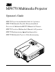
MP8770 Multimedia Projector Operator's Guide MP8770 Projecteur multimédia Guide de l'opérateur MP8770 Multimedia-Projektor Benutzerhandbuch Proyector de Multimedia MP8770 Manual del Usuario MP8770 Proiettore Multimediale Manuale dell'operatore MP8770 Bruksanvisning for multimediaprojektor FOC US + T U M R 3 PO LE + OR MP 877 0 T PR OJ EC 3 TA B M O ZO E Y DB AN ST N O M E N L U A M P P O IN W P E R U T T E M P R E S E T MP8770 Multimedia Projector Gebruiksaanwij
Safeguards ................................................................................................................. 3 Warranty ................................................................................................................. 5 Section 1: Unpack ....................................................................................................... 6 1.1 1.2 1.3 1.4 Section 2: 2.1 2.2 2.3 2.4 Section 3: 3.1 3.2 Section 4: 4.1 4.2 4.3 4.4 4.5 4.6 4.7 4.8 4.9 4.
ENGLISH 2 3M™ Multimedia Projector MP8770 © 3M 2000
Safeguards ENGLISH INTENDED USE Before operating the machine, please read the entire manual thoroughly. The 3M™ Multimedia Projector 8770 was designed, built and tested for use indoors, using 3M™ brand lamps, 3M™ brand ceiling mount hardware and nominal local voltages. This projector is not intended for household use.
ENGLISH LOCATION OF PRODUCT SAFETY LABELS The following safety labels are used on or within the MP8770 projector to alert you to items or areas requiring your attention: CAUTION LASER RADIATIONDO NOT STARE INTO BEAM WAVE LENGTH: 650nm MAX .
LIMITED WARRANTY 3M warrants this product against any defects in material and workmanship, under normal usage and storage, for a period of two years from date of purchase. Proof of purchase date will be required with any warranty claim. In the event this product is found to be defective within the warranty period, 3M's only obligation and your exclusive remedy shall be replacement of any defective parts (labor included).
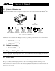
1.1 Contents of Shipping Box The 3M™ MP8770 Multimedia Projector is shipped with the necessary cables required for standard VCR, PC, MAC™ II or laptop computer connections. Carefully unpack and verify that you have all of the items shown below in Figure 1.1.
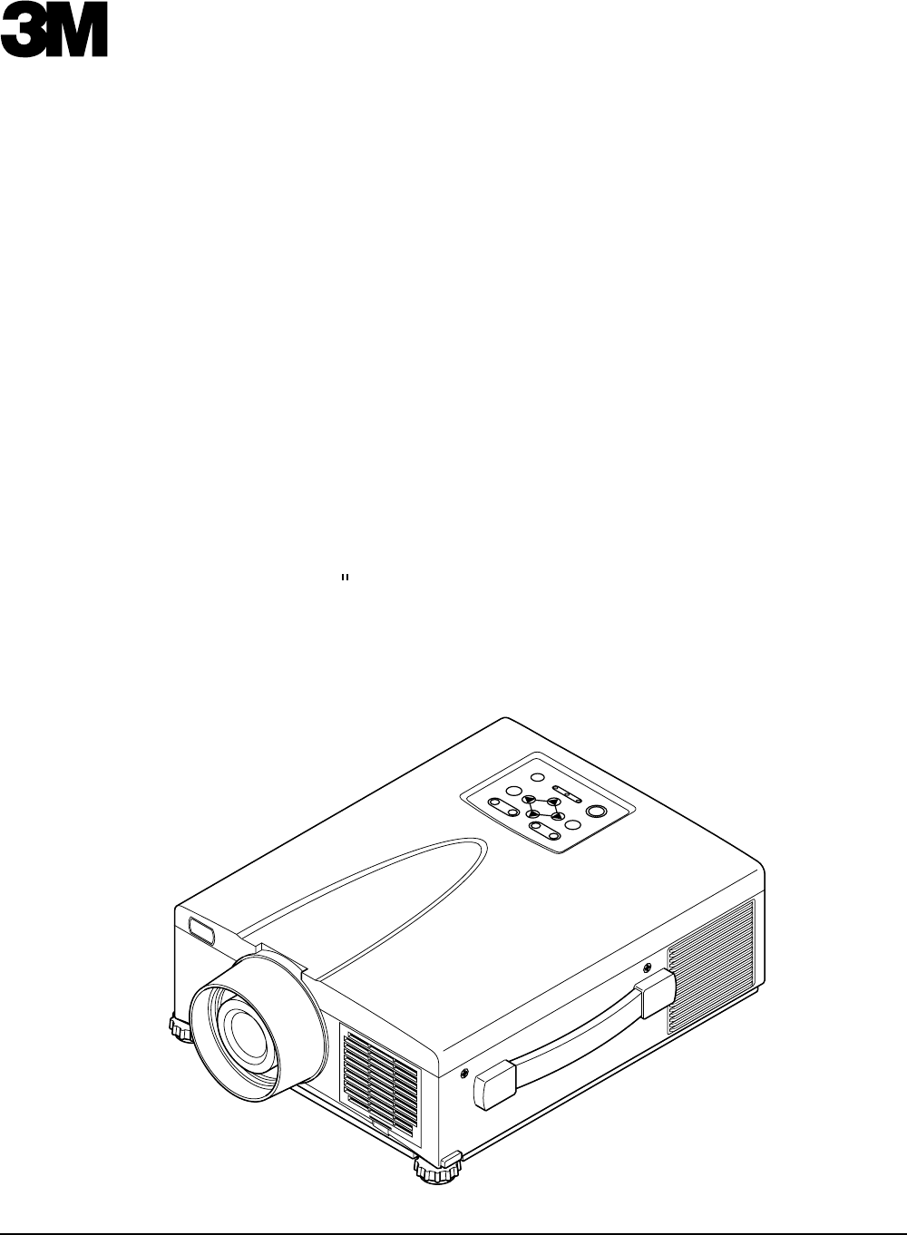
ENGLISH Section 2: Product Description 2.1 Machine Characteristics The MP8770 Multimedia Projector integrates ultra-high bright lamp and polysilicon LCD display technology into a single unit. It accepts input from two different computer sources and one video/audio source and projects a bright, super crisp image. Switching your presentation from a computer input to a video input, and then back to a computer input simply requires the push of a button on the remote control keypad or control panel keypad.
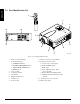
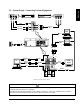
VIDEO RGB LASER STANDBY/ON POSITION 1 RESET MENU FREEZE + MAGNIFY — VOLUME OFF Pin P 2 MUTE BLANK AUTO TIMER + + FOCUS ZOOM — — E W O P U N E N O Y DB AN ST E T U JE C TO R M O ZO M 10 + 12 M S CU FO + R L A IN M P P U T T E M P R E S E T 3 O I 1 RGB IN 2 S-VIDEO IN LE B TA R O P 9 VIDEO IN CONTROL P R O MP 877 0 ENGLISH 2.
WHT RED ENGLISH 2.
ENGLISH 2.3 System Setup - Connecting Various Equipment (continued) Apple™ Desktop Mouse - The Macintosh operating system should recognize the MP8770 as a mouse without any drivers being loaded. VirtualMouse for PC Computer - For IBM™ compatible computers, the operating systems will need to be set to "Serial Mouse," "PS/2 Mouse," or "USB Mouse" to recognize the projector as a mouse pointer device. Change mouse driver information to "Serial Mouse," "PS/2 Mouse," or "USB Mouse.
ENGLISH 2.4 Remote Control Transmitter Identification INPUT LASER Press the VIDEO or RGB button to select the input source. Press again to select the next source. Press and hold down button to project laser pointer. STANDBY/ON Set main power switch to ON. Press STANDBY/ON button to begin projection mode (lamp on) or press and hold button for 1 second to switch to standby mode (lamp off).
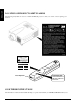
Section 3: Basic Operations ENGLISH 3.1 Projector Startup — ZOOM + — FOCUS + MUTE INPUT O I MENU STANDBY ON RESET U N E M M U T E + STAN DB Y ON S CU FO + ER W PO IN P P M LA U T P M TE R E S E T LAMP POWER TEMP PO AB LE CT ZO OM OR 0 77 P8 M RT PR OJE MP 877 0 EPS-130A Figure 3.1 Projector Controls 2. Turn the POWER SWITCH O I 1. Make all cable connections and line hookups with the power off. of the projector on. The POWER indicator will light up orange.
Section 4: Adjustments and Functions ENGLISH 4.1 How To Use Height Adjustment Feet Adjust the image elevation using the height adjustment at the front of the projector. 1. Raise the front end of the projector so the feet are not touching the table top. 2. Push the lock button to unlock the foot. 3. Extend or retract each foot to the desired height. 4. Release the lock button to lock the foot into position. 5. For fine adjustments, rotate each foot.
ENGLISH 4.2 Plug & Play Function This projector is VESA DDC 1/2B compatible. Plug & play is possible by connecting to a computer that is VESA DDC (Display Data Channel) compatible. Plug & play is a system configured with peripheral equipment including a computer and display, and a compatible operating system. ✔ Note Use the RGB cable included with this projector when using plug & play. With other cables, pins (12) - (15) are sometimes not connected (effective only for RGB1). 4.
ENGLISH 4.6 Menu Navigation MENU Figure 4.2 Menu Button 1. Press any MENU button on projector or remote control MENU button. On-screen menus are displayed on the screen. 2. Select the menu to be adjusted using the MENU ( Selected Menu is highlighted. 3. Select the item to be adjusted using the MENU ( ) buttons or DISC PAD. ) buttons or DISC PAD. Highlighted items may be adjusted. ✔ Note Separate settings are provided for the VIDEO, RGB1 and RGB2 input terminals. Adjustments are saved after power off.
4.7 SETUP ENGLISH The SETUP sub-menu is used to adjust and move the image position. The projector will display either the RGB (Figure 4.4) or Video (Figure 4.5) menu according to the input source being projected. RGB signal input SETUP INPUT IMAGE VOLUME BRIGHT CONTRAST V POSIT H POSIT H PHASE H SIZE COLOR BAL R COLOR BAL B Video signal input OPT. SETUP INPUT IMAGE OPT. VOLUME BRIGHT CONTRAST 121 57 7 800 SHARPNESS COLOR TINT COLOR BAL R COLOR BAL B Figure 4.4 RGB Signal Figure 4.
4.8 INPUT ENGLISH The INPUT sub-menu is used to select the RGB or video input source. The RGB values are shown in figure 4.6. The VIDEO values are shown in figure 4.7. SETUP INPUT RGB VIDEO IMAGE OPT. fH: 48.3 fV: 60 SETUP IMAGE OPT. RGB KHz Hz VIDEO Figure 4.6 Input Menu - RGB AUTO NTSC PAL SECAM NTSC4.43 M-PAL N-PAL Figure 4.
4.9 IMAGE ENGLISH The IMAGE sub-menu is used to change the image characteristics. SETUP INPUT IMAGE OPT. SETUP KEYSTONE KEYSTONE MIRROR MIRROR BLANK BLANK START UP START UP P.IN P. P.IN P. SETUP INPUT IMAGE OPT. KEYSTONE MIRROR BLANK START UP INPUT IMAGE OPT. WHITE BLUE BLACK BLANK START UP P.IN P. INPUT IMAGE OPT. SETUP KEYSTONE MIRROR MIRROR BLANK BLANK P.IN P. OPT. MIRROR KEYSTONE START UP IMAGE KEYSTONE NORMAL H: INVERT V: INVERT H&V: INVERT P.IN P.
4.10 OPT. SETUP INPUT IMAGE ENGLISH The OPT. sub-menu allows you to control communication function. OPT. COM. SPEED COM. BITS TIMER LANGUAGE AUTO OFF SYNC ON G SETUP INPUT IMAGE COM. SPEED COM. BITS TIMER LANGUAGE SETUP OPT. SETUP LANGUAGE AUTO OFF SYNC ON G SYNC ON G IMAGE OPT. OPT. 7N1 8N1 TIMER AUTO OFF INPUT IMAGE COM. BITS SETUP INPUT COM. SPEED COM. SPEED COM. BITS COM. BITS TIMER IMAGE OPT. TIMER 10 min. LANGUAGE SETUP INPUT COM.
5.1 Cleaning the Air Filter ✔ Note Clean the air filter about every 50 hours, if air is restricted due to dust accumulation on filter, the projector may shut down due to overheating. 1. Turn off the MAIN POWER switch of the projector and pull out power cord (1). Let cool for 20 minutes. 2. Push tab (2) and remove the air filter cover (3) from the front of projector. 3. Lift retainer wire (4) and carefully remove foam air filter (5). 4. Vacuum (6) dust and dirt from filter. 5.
Section 6: Lamp ENGLISH 6.1 Lamp The following symptoms may indicate a lamp in need of replacement: • • LAMP indicator lights up red. "CHANGE THE LAMP" message appears on the screen. ✔ Note This lamp contains mercury. Consult your local hazardous waste regulations and dispose of this lamp in a proper manner. 6.2 Display Lamp Operation Hours To determine the lamp operation hours, follow these steps: 1. While the projector is running, press and hold the TIMER button on the remote control for 3 seconds.
6.4 Replacing the Lamp ENGLISH WARNING To reduce the risk of electrical shock, always turn off projector and disconnect power cord before changing lamp. Caution To reduce the risk of severe burns, allow the projector to cool for at least 30 minutes before replacing the lamp. To reduce the risk of cuts to fingers and damage to internal components, use caution when removing lamp glass that has failed and shattered into sharp pieces.
Section 7: Troubleshooting Symptom Cause Solution Power cannot be turned on. • The Main power is not turned on. • The power cord is disconnected. • 60 seconds have not elapsed since the power was turned off. • Turn the MAIN POWER switch on. • Insert the power cord into an AC socket. • Wait 60 seconds before turning on power. No picture and sound. • The setting of the input source is not correct. • RGB/Video/Audio wiring to projector is not correct.
ENGLISH 7.2 Message/Solution Table Error Message Displays Cause Solution NO INPUT IS DETECTED. The projector is not detecting a signal. Check cable connections to input device. Input device not connected to this input mode, switch to next mode. SYNC is out of Range. The horizontal frequency of input signal exceeds projector capability. Switch projector to correct resolution. See Appendix A.5 CHANGE THE LAMP. Nearing end of normal lamp operation CALL A MAINTENANCE time. PERSON.
Section 8: Accessories ENGLISH 8.1 Service Information For product information, product assistance, service information, or to order accessories, please call: In U.S. or Canada: 1-800-328-1371 In other locations, contact your local 3M Sales office. Accessories Part Number Ultra-high performance lamp module, 190 W . . . . . . . . . . . . . . . . . . . . . Power cord (US) . . . . . . . . . . . . . . . . . . . . . . . . . . . . . . . . . . . . . . . . . . . . Power cord (UK) . . . . . . . . . . . . . . . .
Appendix: Technical Information Table of Contents A.1 A.2 A.3 A.4 A.5 A.6 A.7 Technical Specifications Dimensions Projector-to-Screen Distance Connection to the Video Signal Terminal Connection to the RGB Signal Terminal Indicator Status Connection to the Control Signal Terminal A.1 Technical Specifications ✔ Note All specifications are subject to change without notice. Product name Multimedia projector Model Name MP8755 Display system 3 LCD panels, RGB shutter system. Panel size 33 mm (1.3 in.
A.2 Dimensions O I LAMP POWER TEMP PORTABLE PROJECTOR 3 MP8755 STANDBY ON RESET MENU MUTE ZOOM INPUT + FOCUS + 1 AUDIO OUT CONTROL AUDIO IN 1 2 345 mm (13.8 in.) RGB IN 2 RGB OUT USB MOUSE S-VIDEO IN VIDEO IN R AUDIO IN R MONO MD05551 MD05401 289 mm (11.5 in.) 3 MP8755 124 mm 68 mm (5 in.) (2.7 in.) TECHNICAL 31 mm (1.2 in.
A.3 Projector-to-Screen Distance Example of the Multimedia projector and screen installation. Determine picture size and projection distance as shown below. Width 81 cm (32 in.) 122 cm (48 in.) 163 cm (64 in.) 203 cm (80 in.) 244 cm (96 in.) 305 cm (120 in.) 406 cm (160 in.) Screen Size Height 61 cm (24 in.) 91 cm (36 in.) 122 cm (48 in.) 152 cm (60 in.) 183 cm (72 in.) 229 cm (90 in) 305 cm (120 in.) Diagonal 102 cm (40 in.) 152 cm (60 in.) 203 cm (80 in.) 254 cm (100 in.) 305 cm (120 in.
A.4 Connection to the Video Signal Terminal a) Input signal S-VIDEO signal Luminance signal Chrominance signal VIDEO signal 1.0Vp-p, 75Ω termination AUDIO signal b) Signal input terminal 1.0Vp-p, 75 Ω termination 0.286Vp-p (burst signal), 75 Ω termination Input 200mVrms, 20 kΩ below (MAX 3.0Vp-p) Output 0~200mVrms, 1k Ω Chrominance signal Ground Luminance signal Ground S VIDEO input (Mini DIN 4pin) ✔ Note Video input signal terminals have priority in the following order: 1.
c) Example of computer signal Resolution HxV Refresh Rate Horizontal Standard Type Note Frequency Display Dots HxV 640 x 350 85.1 Hz 37.9 kHz VGA-1 800 x 490 640 x 400 56.4 Hz 24.8 kHz NEC PC9800 800 x 560 640 x 400 85.1 Hz 37.9 kHz VGA-2 800 x 560 640 x 480 85.0 Hz 43.3 kHz VESA VGA-3 (85 Hz) 800 x 600 640 x 480 59.9 Hz 31.5 kHz VESA VGA-3 800 x 600 640 x 480 66.7 Hz 35.0 kHz MAC 13" 800 x 600 640 x 480 72.8 Hz 37.
A.6 Indicator Status The POWER, LAMP and TEMP indicators will light or blink in the following cases: POWER LAMP TEMP MEANING REMEDY INDICATOR INDICATOR INDICATOR Lights orange Turns off Turns off Standby mode Normal Flashes green Turns off Turns off During warm up Normal Lights green Turns off Turns off During operation Normal Flashes orange Turns off Turns off During cooling down Normal Lights red Lights red Turns off Lamp does not light.
A.7 Connection to the Control Signal Terminal a) Mouse emulation (1) While the projector and computer are turned OFF, connect the projector and the mouse terminal of computer using an appropriate cable (PS/2, Serial or ADB). (2) Turn ON the projector. (3) Turn ON the computer. (4) Select the correct mouse driver for the application. See computer's User Manual for this procedure.
A.7 Connection to the Control Signal Terminal (continued) Serial mouse Projector D-sub 15pin (Female) 1 5 6 SEL0 RTS 10 11 15 GND RD TD 1 2 3 4 5 6 7 8 9 10 11 12 13 14 15 1 2 3 4 5 6 7 8 9 Computer CD RD TD DTR GND DSR RTS DTS RI (male) D-sub 9pin 1 5 6 9 Serial Mouse cable RS-232 Control Cable (not included with basic packout) This cable is used to directly control the projector without using the Remote Control or Operator's Panel.
A.7 Connection to the Control Signal Terminal (continued) USB Mouse Cable This cable is used to connect the projector and computer to allow computer mouse control via the projector's remote control buttons. Connect the cable, select the input source where the computer is to be connected and start the mouse functions.
Serial Command Codes All numbers in this document are in Hexadecimal. You must send at the same communication setting as the projector and use a null modem serial cable to connect to the projector. There are four types of messages: 1) ASK, 2) REPLY, 3) SET and 4) DEFAULT. Ask Code: User: 20 XX XX is the attribute you are checking. Projector: 1Y XX Y bytes of data This is a reply code. The Y is the number of extra bytes that come after the command. The XX is the same as in the Ask code.
Serial Command Code Table Command Code 05 # Bytes 1 Communication 06 1 Power 11 1 Zoom 12 1 Focus 13 1 Mirror 14 1 Magnify 15 set Command 1 Ask Command 1 Freeze 16 1 Input 21 1 Video Type 22 2 Volume Mute 23 24 1 1 Brightness 31 3 Contrast 32 3 © 3M 2000 Data Code 00 01-7F 0X 1X X0 X1 X2 X3 X4 3E 3F 01-3F 41-7F 01-3F 41-7F 00 01 02 03 Meaning Stop mouse function Enable mouse function 8N1 7N1 1200 bps 2400 bps 4800 bps 9600 bps 19200 bps Power off Power on Zoom + Zoom
TECHNICAL Serial Command Code Table (con't) Function Color Command Code 33 # Bytes 3 Tint 34 3 Sharpness 35 3 H. Phase 37 3 H. Position 38 4 H. Size 36 4 V.
Important Notice All statements, technical information, and recommendations related to 3M’s products are based on information believed to be reliable, but the accuracy or completeness is not guaranteed Before using this product, you must evaluate it and determine if it is suitable for your intended application. You assume all risks and liability associated with such use.