MP8780 Multimedia Projector Operator's Guide MP8780 Projecteur multimédia Guide de l'opérateur MP8780 Multimedia-Projektor Benutzerhandbuch Proyector de Multimedia MP8780 Manual del Usuario MP8780 Proiettore Multimediale Manuale dell'operatore MP8780 Bruksanvisning for multimediaprojektor MP8780 Multimedia Projector Gebruiksaanwijzing EPS-57A
Safeguards ................................................................................................................. 3 Warranty ................................................................................................................. 5 Section 1: Unpack ....................................................................................................... 6 1.1 1.2 1.3 1.4 Section 2: 2.1 2.2 2.3 2.4 Section 3: 3.1 3.2 Section 4: 4.1 4.2 4.3 4.4 4.5 Section 5: 5.1 Section 6: 6.1 6.
ENGLISH 2 3M™ Multimedia Projector MP8780 © 3M 1999
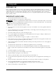
INTENDED USE Before operating the machine, please read the entire manual thoroughly. The 3M™ Multimedia Projector 8780 was designed, built and tested for use indoors, using 3M™ brand lamps, 3M™ brand ceiling mount hardware and nominal local voltages. This projector is not intended for household use. The use of other replacement lamps, outdoor operation or different voltages has not been tested and could damage the projector or peripheral equipment and/or create a potentially unsafe operating condition.
ENGLISH LOCATION OF PRODUCT SAFETY LABELS Safety labels are used on or within the 8780 projector to alert you to items or areas requiring your attention. DO NOT REMOVE SCREWS EXCEPT USER SERVICE SCREWS " " HIGH TEMPERATURE MAY CAUSE BURNS. REPLACE THE LAMP UNIT ONLY AFTER IT HAS COOLED. REPLACE WITH THE SAME LAMP UNIT. HIGH VOLTAGE MAY CAUSE AN ELECTRIC SHOCK AND ULTRAVIOLET. REPLACE THE LAMP AFTER FIRST REMOVING THE POWER PLUG FROM THE OUTLET. THIS COVER IS PROVIDED WITH AN INTERLOCK.
LIMITED WARRANTY 3M warrants this product against any defects in material and workmanship, under normal usage and storage, for a period of two years from date of purchase. Proof of purchase date will be required with any warranty claim. In the event this product is found to be defective within the warranty period, 3M's only obligation and your exclusive remedy shall be replacement of any defective parts (labor included).
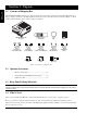
Section 1: Unpack VGA Cable (15-15 pin M/M) R VIDEO L SELECT BACK LIGHT ON 1 2 3 4 5 6 OFF DRAG MENU RGB RESET MUTE 3-Conductor Video/Audio Cable ZOOM BLANK MP8780 Multimedia Projector FOCUS VOLUME The 3M™ MP8780 Multimedia Projector is shipped with the necessary cables required for standard VCR, PC, MAC™ II or laptop computer connections. Carefully unpack and verify that you have all of the items shown below in Figure 1.1.
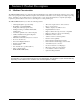
Section 2: Product Description ENGLISH 2.1 Machine Characteristics The MP8780 Multimedia Projector integrates ultra-high bright lamp and polysilicon LCD display technology into a single unit. It accepts input from three different computer sources and three video/audio sources and projects a bright, super crisp image. Switching your presentation from a computer input to a video input, and then back to a computer input simply requires the push of a button on the remote control keypad or control panel keypad.
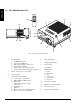
ENGLISH 2.2 Part Identification List STANDBY/ON MUTE BLANK ZOOM FOCUS VOLUME MENU VIDEO BACK LIGHT RESET RGB 13 2 DRAG SELECT L R 1 3 12 9 2 O I 11 10 4 8 5 7 6 EPS-59A Figure 2.2 Identifying MP8780 Parts 1. 8 Operation Panel a) STANDBY/ON button b) Input Source: RGB/Video c) Mute, Blank, Volume, Zoom, Focus d) Display Menu (On/Off) e) Select button (select displayed value) f) Arrow Direction buttons (left/right or up/down) 2. Remote Control Sensors (front/back) 3.
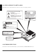
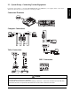
2.3 System Setup - Connecting Various Equipment ENGLISH It only takes a few minutes to connect the 3M™ Multimadia Projector MP8780 to your computer, VCR, or other device. Always disconnect the projector power before connecting any cables.
ENGLISH 2.
ENGLISH 2.4 Remote Control Transmitter Identification STANDBY/ON MUTE Set main power switch to ON. Press STANDBY/ON button to begin projection mode (lamp on) To turn lamp off, press STAND/ON then select YES on Shut Down screen. Select NO to continue running. Press button to turn the mute function (speaker sound) ON/OFF. STANDBY/ON MUTE BLANK Press (+) or (-) to adjust the image sharpness.
Section 3: Basic Operations ENGLISH 3.1 Projector Startup Menu Select + + + Zoom Focus Volume – – – RGB Standby/On Blank Video O I O I Figure 3.1 Projector Controls 1. Make all cable connections and line hookups with the power off. 2. Turn the POWER SWITCH 3. Press the STANDBY/ON button . The ON indicator blinks (green) and then lights (green). The ON indicator will blink green during warm-up and lamp ignition.
Section 4: Adjustments and Functions STANDBY/ON MUTE BLANK + + + ZOOM FOCUS VOLUME – – – RGB TIMER VIDEO MENU MAGNIFY FREEZE ENGLISH 4.1 Menu Navigation MENU DRAG + L SELECT – R LIGHT Figure 4.1 Menu Button 1. Press MENU button on projector or remote control. On-screen menus are displayed on the screen. 2. Select the sub-menu (SETUP, IMAGE, OPTION) to be adjusted using the SELECT ( ) buttons or MINI-JOY STICK. Selected Menu is highlighted. 3.
ENGLISH 4.3 SETUP The SETUP sub-menu is used to adjust and move the image position. The projector will display either the RGB (Figure 4.4) or Video (Figure 4.5) menu according to the input source being projected. SETUP BRIGHTNESS SETUP BRIGHTNESS IMAGE CONTRAST IMAGE CONTRAST OPTION POSITION OPTION COLOR PHASE TINT H SIZE SHARPNESS AUTO GAMMA MAC MODE SCAN MODE GAIN VCR MODE Figure 4.4 RGB Signal Figure 4.
ENGLISH 4.4 IMAGE The IMAGE sub-menu is used to change the image characteristics. SETUP PIP IMAGE MIRROR OPTION MESSAGE COLOR TEMP SETUP PIP SETUP PIP IMAGE MIRROR IMAGE MIRROR OPTION MESSAGE OPTION MESSAGE COLOR TEMP COLOR TEMP SETUP PIP SETUP PIP IMAGE MIRROR IMAGE MIRROR OPTION MESSAGE OPTION MESSAGE COLOR TEMP COLOR TEMP Figure 4.
ENGLISH 4.5 OPTION The OPT. sub-menu allows you to control communication function.
ENGLISH 4.
ENGLISH Section 5: Maintenance 5.1 Cleaning the Air Filter ✔ Note Clean the air filter about every 50 hours, if air is restricted due to dust accumulation on filter, the projector may shut down due to overheating. 1. Turn off the MAIN POWER switch of the projector and pull out power cord. Let cool for 20 minutes. 2. Remove the air filter from the bottom of projector. Push down on tabs (1), open cover (2) and slide cover off (3). 3. Turn cover over and carefully remove foam air filter screen (4). 4.
Section 6: Lamp ENGLISH 6.1 Lamp The following symptoms may indicate a lamp in need of replacement: • LAMP indicator lights up red. • "CHANGE THE LAMP" message appears on the screen. ✔ Note This lamp contains mercury. Consult your local hazardous waste regulations and dispose of this lamp in a proper manner. 6.2 Display Lamp Operation Hours The lamp operating hours will display when the projector is powered up.
6.3 Replacing the Lamp ENGLISH WARNING To reduce the risk of electrical shock, always turn off projector and disconnect power cord before changing lamp. Caution To reduce the risk of severe burns, allow the projector to cool for at least 45 minutes before replacing the lamp. To reduce the risk of cuts to fingers and damage to internal components, use caution when removing lamp glass that has failed and shattered into sharp pieces.
Section 7: Troubleshooting Symptom Cause ENGLISH 7.1 Symptom/Solution Table Solution Power cannot be turned on. • The Main power is not turned on. • The power cord is disconnected. • 90 seconds have not elapsed since the power was turned off. • Turn the MAIN POWER switch on. • Insert the power cord into an AC socket. • Wait 90 seconds before turning on power. No picture and sound. • The setting of the input source is not • Set the correct input using the input select button of correct.
ENGLISH Section 8: Accessories 8.1 Service Information For product information, product assistance, service information, or to order accessories, please call: In U.S. or Canada: 1-800-328-1371 In other locations, contact your local 3M Sales office. -Accessories Part Number Metal Halide lamp module, 440 W . . . . . . . . . . . . . . . . . . . . . . . . . . . . . Power cord (US) . . . . . . . . . . . . . . . . . . . . . . . . . . . . . . . . . . . . . . . . . . . . Power cord (UK) . . . . . . . . . . . .
Appendix: Technical Information Table of Contents A.1 A.2 A.3 A.4 A.5 A.6 A.7 Technical Specifications Dimensions Projector-to-Screen Distance Connection to the Video Signal Terminal Connection to the RGB Signal Terminal Indicator Status Connection to the Control Signal Terminal A.1 Technical Specifications ✔ Note All specifications are subject to change without notice. Product name Multimedia projector Model Name MP8780 Display system 3 LCD panels, strip pixel configuration. 46 mm (1.8 in.
USB MOUSE SERIAL L R VS RGB3/VIDEO3 VIDEO2 R L VIDEO1 IN PUT RGB1 L R L RGB2 R L HS R/Y(CV) G/U B/V R L RGB R OUT PUT A.2 Dimensions – – + + O I 495 mm (19.8 in.) 520 mm (20.8 in.) – + 430 mm (17.2 in.) LAMP TEMP FAN COVER CHANGE LAMP POWER MP8780 TECHNICAL 222 mm (8.9 in.
A.3 Projector-to-Screen Distance Example of the Multimedia projector and screen installation. Determine picture size and projection distance as shown below. Width 81 cm (32 in.) 130 cm (48 in.) 180 cm (64 in.) 230 cm (80 in.) 280 cm (96 in.) 354 cm (120 in.) 179 cm (160 in.) 728 cm (287 in.) Screen Size Height 61 cm (24 in.) 91 cm (36 in.) 122 cm (48 in.) 152 cm (60 in.) 183 cm (72 in.) 229 cm (90 in) 305 cm (120 in.) 457 cm (180 in.) Diagonal 102 cm (40 in.) 152 cm (60 in.) 203 cm (80 in.
A.4 Connection to the Video Signal Terminal a) Input signal Luminance signal Chrominance signal S-VIDEO signal 1.0Vp-p, 75 Ω termination VIDEO signal AUDIO signal b) Signal input terminal 1.0Vp-p, 75 Ω termination 0.286Vp-p (burst signal), 75 Ω termination Input 140mVrms, 46 k Ω (MAX 7.0Vp-p) Output 0-140mVrms, 680 Ω Chrominance signal Ground Luminance signal Ground S VIDEO input (Mini DIN 4pin) ✔ Note Video input signal terminals have priority in the following order: 1.
c) Example of computer signal Scan Frequency Dot Clock H-Size Resolution H (kHz) V (Hz) (MHz) Computer 1 2 3 4 4 4 5 5 5 6 7 8 9 10 11 12 13 14 15 16 17 18 19 20 21 22 23 24 25 26 27 28 29 30 31 32 33 34 35 36 37 38 39 39 40 41 780 940 848 900 800 800 936 832 832 800 896 832 840 832 1024 1056 1040 1056 1048 1152 1344 1328 1312 1376 1312 1328 1264 1472 1472 1600 1568 1456 1500 1800 1680 1728 1688 1688 1728 1688 2160 2160 2200 1100 1650 2200 320x480i 384x576i 640x400 720x400 640x400 640x350 720x400 6
c) Example of computer signal (continued) Note 1: MAC adapter is necessary to set the resolution mode. Projector is compatible with 13 inch mode and 16 inch mode. Set all dip switches OFF except those indicated below. MAC 13" mode = switch 1 and 2 are ON MAC 16" mode = switch 2 and 4 are ON (Example of 16 inch mode) Note 2: Some input sources may not be displayed properly because they are not compatible with the projector. A.
A.7 Connection to the Control Signal Terminal a) Mouse emulation (1) While the projector and computer are turned OFF, connect the projector and the mouse terminal of computer using an appropriate cable (PS/2, Serial or ADB). (2) Turn ON the projector. (3) Turn ON the computer. (4) Select the correct mouse driver for the application. See computer's User Manual for this procedure.
A.7 Connection to the Control Signal Terminal (continued) Serial mouse Projector Mini Din 9-pin (Male) 7 8 9 3 4 5 6 1 2 1 2 3 4 5 6 7 8 9 Shield Computer 1 2 3 4 5 6 7 8 9 Shield D-sub 9-pin (Female) 1 5 6 9 RS-232 Control Cable (not included with basic packout) This cable is used to directly control the projector without using the Remote Control or Operator's Panel. TECHNICAL Not available for this printing.
A.7 Connection to the Control Signal Terminal (continued) USB Mouse Cable This cable is used to connect the projector and computer to allow computer mouse control via the projector's remote control buttons. Connect the cable, select the input source where the computer is to be connected and start the mouse functions.
A.8 Serial Inferface Command Codes Command Code Formats All codes in this document are in ASCII Text. In order to get this to work you must send at the same communication setting as the projector. This should be 9600 8N1. For the rest of this document CR is a carriage return which is code 13. There are two types of commands that can be sent to the projector. They are Write or Read commands.
Serial Inferface Command Codes (continued) Function Power On/Off Code Write Codes D00W00 D00W01 Read Codes D00R Source Selection Write Codes D02W01 D02W02 D02W03 D02W11 D02W12 D02W13 D03W00 Read Codes D02R Volume Control Focus Control Zoom Mute Write Codes D04W00 to D04W14 Read Codes D04R Write Codes D05W00 D05W01 D05W10 D05W11 D05W20 Write Codes D06W00 D06W01 D06W10 D06W11 D06W20 Write Codes D07W00 D07W01 Read Codes D07R Blank Write Codes D08W00 D08W01 Read Codes D08R © 3M 1999 Meaning Power O
A.8 Serial Inferface Command Codes (continued) Function Contrast Brightness Tint (Hue) Color (Saturation) Sharpness Gamma PC Mode MAC Mode Code Write Codes D12W00 to D12W14 TECHNICAL A-12 Set contrast level to a value between 00 and 14 hex. This corresponds to 20 possible settings.
Serial Inferface Command Codes (continued) Function Display Position Code Write Codes D36W00 to D36WFE D37W00 to D37WFE D38W00 H-Size On–Screen Displays Language Selection Returns: 00 to FE vertical position 00 to FE horizontal position The 00 to 80 denotes the deviation of clock numbers from the standard in one horizontal period. “40” is zero, “00” is 64 and “80” is +64 decimal.
A.
Important Notice All statements, technical information, and recommendations related to 3M’s products are based on information believed to be reliable, but the accuracy or completeness is not guaranteed Before using this product, you must evaluate it and determine if it is suitable for your intended application. You assume all risks and liability associated with such use.