S40/X40 Multimedia Projector Operator's Guide TECHNICAL
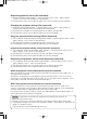
S40/X40-TECH 03.8.21 3:50 PM ページ 1 TECHNICAL SIGNAL CONNECTOR PIN ASSIGNMENT s-video rgb D-sub 15-pin Shrink Pin No Signal Mini Din 4-pin Pin No Signal 1 Video input Red 9 - 2 3 4 5 6 7 Video input Green Video input Blue Ground Ground Red Ground Green 10 11 12 13 14 15 8 Ground Blue Mini Din 4-pin Pin No Signal Ground SDA (DDC) H. sync./ Composite sync. Vertical sync SCL (DDC) 1 2 Color: 0.286Vp-p (NTSC, burst signal), 75Ω terminator 0.
S40/X40-TECH 03.8.21 3:50 PM ページ 2 EXAMPLE OF COMPUTER SIGNAL Display mode Resolution H×V fH (kHz) fV (Hz) Rating Signal mode S40 X40 720 × 400 37.9 85.0 VESA TEXT Zoom in Zoom in 640 × 480 31.5 59.9 VESA VGA (60Hz) Zoom in Zoom in 640 × 480 35.0 66.7 Mac13"mode Zoom in Zoom in 640 × 480 37.9 72.8 VESA VGA (72Hz) Zoom in Zoom in 640 × 480 37.5 75.0 VESA VGA (75Hz) Zoom in Zoom in 640 × 480 43.3 85.0 VESA VGA (85Hz) Zoom in Zoom in 800 × 600 35.2 56.
S40/X40-TECH 03.8.21 3:50 PM ページ 3 INITIAL SET SIGNALS The following signals are used for the initial settings. The signal timing of some computer models may be different. In such case, refer to adjust the V.POSIT and H.POSIT of the menu. Back porch b Front porch d Display interval c Back porch b Front porch d Display interval c DATA DATA HSYNC VSYNC Sync a Computer / Signal Sync a Horizontal signal timing (µs) TEXT a 2.0 b 3.0 c 20.3 d 1.
S40/X40-TECH 03.8.21 3:50 PM ページ 4 RS-232C COMMUNICATION (1) Turn off the projector and computer power supplies and connect with the RS-232C cable. (2) Turn on the computer power supply and after the computer has started up, turn on the projector power supply.
S40/X40-TECH 03.8.21 3:50 PM ページ 5 Requesting projector status (Get command) (1) Send the request code Header + Command data (‘02H’+‘00H’+ type (2 bytes) +‘00H’+‘00H’) from the computer to the projector. (2) The projector returns the response code ‘1DH’+ data (2 bytes) to the computer. Changing the projector settings (Set command) (1) Send the setting code Header + Command data (‘01H’+‘00H’+ type (2 bytes) + setting code (2 bytes)) from the computer to the projector.
RS-232C COMMUNICATION (continued) Command data chart Names Blank Color Operation type Set CRC Action Type Setting code Blue BE EF 03 06 00 CB D3 01 00 00 30 03 00 White BE EF 03 06 00 6B D0 01 00 00 30 05 00 Black BE EF 03 06 00 9B D0 01 00 00 30 06 00 BE EF 03 06 00 08 D3 02 00 00 30 00 00 Normal BE EF 03 06 00 C7 D2 01 00 01 30 00 00 H Inverse BE EF 03 06 00 57 D3 01 00 01 30 01 00 V lnverse BE EF 03 06 00 A7 D3 01 00 01 30 02 00 H&V Inverse
Names Operation type H.Position Reset Execute BE EF 03 H.
Command data chart (continued) Names Operation type Command data Header CRC Contrast Type Setting code Get BE EF 03 06 00 FD D3 02 00 04 20 00 00 Increment BE EF 03 06 00 9B D3 04 00 04 20 00 00 Decrement BE EF 03 06 00 4A D2 05 00 04 20 00 00 Get BE EF 03 06 00 01 D2 02 00 05 20 00 00 Increment BE EF 03 06 00 67 D2 04 00 05 20 00 00 Decrement BE EF 03 06 00 B6 D3 05 00 05 20 00 00 Get BE EF 03 06 00 45 D2 02 00 06 20 00 00 Increment BE EF 03
Names Operation type Tint Command data Header Get BE EF 03 06 00 CRC Action Type Setting code 49 73 02 00 03 22 00 00 Increment BE EF 03 06 00 2F 73 04 00 03 22 00 00 Decrement BE EF 03 06 00 FE 72 05 00 03 22 00 00 Set Auto BE EF 03 06 00 9E 75 01 00 00 22 0A 00 NTSC BE EF 03 06 00 FE 71 01 00 00 22 04 00 PAL BE EF 03 06 00 6E 70 01 00 00 22 05 00 SECAM BE EF 03 06 00 6E 75 01 00 00 22 09 00 NTSC 4.
Intended Use Before operating this machine, please read this entire manual thoroughly. The 3MTM Multimedia Projectors are designed, built, and tested for use indoors, using 3M lamps, 3M ceiling mount hardware, and nominal local voltages. The use of other replacement lamps, outdoor operation, or different voltages has not been tested and could damage the projector peripheral equipment and/or create a potentially unsafe operating condition.