Version 1.
©2011 3M Cogent, Inc. All rights reserved. This document contains commercial information and trade secrets of Cogent, Inc. which are confidential and proprietary in nature and are subject to protection under law. Access to the information contained herein, howsoever acquired and of whatsoever nature, will not entitle the accessor thereof to acquire any right thereto. The data subject to this restriction are contained in all sheets of this document.
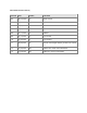
Document Revision History Version Date Author Comment 0.4 08/25/2010 RC Initial version JL Updates 0.5 0.6 05/03/2011 CC Updates 0.7 05/09/2011 MH Updates 0.8 05/11/2011 JL updates 0.9 05/12/2011 CC Final review 1.0 07/20/2011 JL Final release 1.1 09/06/2011 RS Include unmanaged default password in section 7.1 1.2 10/26/2011 MH Update OTG cable recommendation 1.
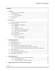
Contents 1 Overview 1.1 1.2 1.3 1.4 2 3 3.5 3.6 3.7 3.8 5 Proprietary 23 Manually Configuring the MiY-Device’s Connection................................................ 23 4.1.1 TCP/IP Configuration ................................................................................. 23 4.1.2 Configuring RS485 Connection Settings ..................................................... 28 Registering the Reader with MiY-Security Manager Contents 11 Accessory List ......................................
.1 6 Upload Package via USB 6.1 7 7.3 7.4 A B B.4 Contents Proprietary 61 Positioning the Finger on the Fingerprint Sensor.................................................... 61 Capturing High-Quality Fingerprints ...................................................................... 62 Maintenance and Troubleshooting B.1 B.2 B.3 57 Verifying Users with the MiY-Search and MiY-Card.................................................. 57 Verifying Users with the MiY-ID Device......................
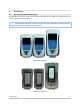
1 Overview 1.1 MiY Product Line Introduction The Cogent MiY product line offers a complete range of highly sophisticated, accurate, and customizable biometric physical access control terminals which provide access security in a variety of environments. All the devices of the MiY product line are designed to perform fast and efficient authentication and entry. Fingerprint data for users who no longer have access can be easily erased from the system in real-time.
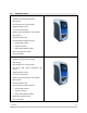
1.2 Standard Features MiY-Search • Sandbox API framework support • IP65 design • Non-mechanical 12-key keypad • Rugged optical sensor • 2.
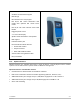
MiY-ID • Sandbox API framework support • IP64 design • Non-mechanical 21-key keypad • Full PC/SC ISO 14443 contactless card reader with optional ISO 15693 iClass reader • Full PC/SC ISO 7816 Contact Smart Card Reader • Rugged optical sensor • 2.
1.3 Types of Users MiY devices provide access privileges for two types of users: • Standard Users: Can access the Verify operation mode only. Enroll and Delete functions can also be performed, but only in the presence of and with the assistance of an Administrator. • Administrators: Possess privileges for all operation modes available for the MiY devices, including setting the Verify, Enroll, and Delete modes using an Administrator Card where applicable. 1.
2 MiY Devices 2.1 MiY-Search and MiY-Card Overview The MiY-Devices come in three versions: MiY-Search, MiY-Card, and MiY-ID. These devices have similar appearances and functions. NOTE: The MiY-Search and MiY-Card share the same physical specifications. However, the MiYCard and MiY-ID come equipped with card readers.
2.2 Physical Features MiY physical access devices are housed in a rugged plastic casing and can provide various modes for identification, verification and multi-factor authentication. The following subsections provide an introduction to the physical characteristics of MiY devices. 2.2.1 Contactless Card Reader The MiY-Card and MiY-ID have guidance LEDs on the contactless reader that help direct the user’s attention to the top of the device during a contactless card read. MiY-Card Front View 2.2.
MiY-Card and MiY-Search MiY-Card 12 Keys 2.2.4 21 Keys Fingerprint Sensor MiY-Devices have a built-in fingerprint sensor that is rated for outdoor use. Fingerprint Sensor 2.2.
2.2.6 Admin Port and Reset Button The bottom of the device has a weather protection rubber cover that protects the Admin port and reset button. Admin Port and Reset Button 2.2.7 Wall Mount The stainless steel mounting bracket can be attached to a single gang box or double gang box. MiY-Devices have a hinge at the bottom which allows installers to latch the device on the wall and open the back panel for easy wiring.
Back Panel and Connections The back panel of MiY devices can be opened to expose the internal connections.
2.2.8 USB Ports The MiY device has two (2) USB ports that are configurable. The device has a USB host port and OTG USB client port. 2.2.8.1 USB Host Port The USB host port is only accessible from the back panel of the device. The USB host port is used to integrate additional USB components to the device, such as a camera, by adding a driver for the component to the firmware and updating GateApp’s to use the new component. 2.2.8.
3 Installing a MiY Device 3.1 Accessory List The following items are included in the MiY package: • Terminal blocks • Security screws (2) • Security screw tool • Installation CD • Installation Guide 3.2 Mounting the Bracket To mount the wall bracket: 1 Screw the bracket into the gang box in the wall based the below images. The MiY-Card and MiY-Search bracket attaches to a single gang box, where as the MiY-ID bracket will work on either a single gang or double gang box.
2 Place the device’s bracket hinge pin on the hooked mounting bracket Attaching the Hinge Pin to the Mounting Bracket 3.3 Wiring Installation Lift the compression panel so that the terminal blocks and connectors are exposed. See below for a diagram which shows the connectors available under the compression panel. The Ethernet port is a PoE port that can deliver both power and communication to MiY devices and allows the devices to function without requiring additional 12V cables.
Pin descriptions for Terminal Blocks A, B, and C: Pin Number Description A1 Earth Ground A2 Relay + A3 Relay - A4 Power GND A5 Power (12 V DC) Low-Profile Terminal Block A Pin Number Description B1 RS-485 (-) B2 RS-485 (+) B3 Line Trigger (DRV_Out) B4 LED-like Panel Input (0) B5 LED-like Panel Input (1) Low-Profile Terminal Block B Pin Number Description C1 Wiegand Output Data 0 C2 Wiegand Output Data 1 C3 Wiegand Output GND C4 Wiegand Input GND C5 Wiegand Input Data 0 C6 Wieg
3.4.1 Connecting the Power Supply to the Terminal Blocks To connect 12V power to the MiY-device: 1 Take the terminal block and connect the 12V wire to the last position and the ground wire to the next position. Terminal Positions (Red: 12V, Black: Ground) 2 Take a small flat-head driver and tighten the screws to hold the wires in-place Tightening Screws 3 Connect the terminal block to the terminal block connector A. When power is available, the MiY-Device will turn on. 3.4.
PoE-Enabled Hub Connected Directly to MiY Device 2 Connect a CAT-5 Ethernet cable between the Ethernet port of the MiY device and a midspan power injector unit Hub Connected to MiY Devices via Midspan 3 -Installing a MiY Device Proprietary 15
3.5 Panel-in Wiring The Panel in wiring can be done by placing the wire into terminal block slot (B4) LED – like Panel Input (0) as well as connecting a ground cable from the panel to either terminal block slot (A4) Power GND or (C4) Wiegand Input GND. If your device is connected via Wiegand to an access control panel, then you can connect a wire from (C3) Wiegand Output GND to (C4) Wiegand Input GND.
3.7 Securing the MiY Devices on the Wall Once the wires are connected, run the wires downwards so that they pass the compression pad. The wires should be evenly distributed to create the best possible seal between the top and bottom compression pads WARNING: Grouping wires together can create a gap, allowing water and dust to enter the device. Also not screwing down the compression pad will reduce the Industrial Protection capabilities of the device.
Proper Wire Distribution 3 -Installing a MiY Device Proprietary 18
1 Screw down and tighten the screws on the compression panel so the compression pads conform to the wires and create a seal Compression Panel Screw Position 2 Pivot the device on the bracket hinge and bring it up over the wall mount.
3 Secure the device by using the security-screw driver to insert and tighten the security screws on both sides of the MiY-Device. Location of Security Screws 4 Verify that the security screws are in place by attempting to rotate the device off the mounting bracket by its hinge at the bottom. The device should feel secured and not loose. 3.8 Balancing the Termination For the last device on the line, you should add a termination resister to the terminal block before plugging it into the device.
A good rule of thumb is that if the propagation delay of the data line is much less than one bit width, termination is not needed. This rule makes the assumption that reflections will damp out in several trips up and down the data line. Since the receiving UART will sample the data in the middle of the bit, it is important that the signal level be solid at that point.
Parallel and AC Termination 3 -Installing a MiY Device Proprietary 22
4 Network Installation MiY network installation is an automatic process. For details, see the MiY Security Manager User Guide. However, should a manual installation be necessary, the following subsections contain details on manual network configuration for MiY devices. 4.1 Manually Configuring the MiY-Device’s Connection This procedure is performed from the Network screen in the Cogent GateApp. For more information on using the Cogent GateApp, refer to the section Cogent GateApp for Administrators. 4.
2 From the Device Info screen, select Network. The Network screen will be displayed. Network Screen 3 From the Network screen, you can view the current network configuration. Select Change to modify the configuration. The Protocol screen will be displayed.
4 From the Protocol screen, select the Ethernet protocol and select OK. The Mode screen will be displayed Mode Screen 5 From the Mode screen, select the DHCP or Static mode and select OK. • If Static, the IP Address screen will be displayed • If DHCP, skip to step 8. The TCP Port screen will be displayed IP Address Screen 6 From the IP Address screen, enter each Octet and select Next to move to the next Octet. Select OK when the IP Address is complete. The Subnet screen will be displayed.
Subnet Screen 7 From the Subnet screen, enter each Octet and select Next to move to the next Octet. Select OK when the Subnet is complete. The Gateway screen will be displayed. Gateway Screen 8 From the Gateway screen, enter each Octet and select Next to move to the next Octet. Select OK when the Gateway is complete. The TCP Port screen will be displayed.
TCP Port Screen 9 From the TCP Port screen, set the port and select OK. The TLS Port screen will be displayed. TLS Port Screen 10 From the TLS Port screen, set the port and select OK. The Network Review screen will be displayed.
Network Review Screen 11 From the Network Review screen, select Save to commit the changes or Cancel to abort the changes. 4.1.2 Configuring RS485 Connection Settings To configure RS485 connection settings: 1 From the Admin Menu screen select Device Info. The Device Info screen will be displayed. Device Info Screen 2 From the Device Info screen, select Network.
Network Screen 3 From the Network screen, you can view the current network configuration. Select Change to modify the configuration. The Protocol screen will be displayed Protocol Screen 4 From the Protocol screen, select the RS485 protocol and select OK. The Baud Rate screen will be displayed.
Baud Rate Screen 5 From the Baud Rate screen, select the baud rate and select OK. The Network Review screen will be displayed. Network Review Screen 6 From the Network Review screen, select Save to commit the changes or Cancel to abort the changes.
5 Registering the Reader with MiY-Security Manager 5.1 Basic Zone Creation Once the MiY device has been installed, use MiY Security Manager software to register the device and set up zones. For details on managing devices, see the MiY Security Manager User Guide.
This page was intentionally left blank.
6 Upload Package via USB NOTE: The Device Admin Utility can always export data from a device, but can only send data to a device when the device is in standalone mode. MiY devices are shipped in Standalone mode (no MiY-Server or MiY-Security Manager required) and remain in standalone mode until registered to a server. Once registered to a server, the device is considered to be in managed mode because it is controlled by the server.
PC Device Manager 4 From the Device Admin Utility, select Indicate to verify you are connecting to the correct device. The device LEDs should flash and you should hear a sound. 5 Select Connect to connect to the device. NOTE: If the connect button is disabled, communication between the device and the PC or laptop is not functioning correctly.
Connect Button 6 After successfully connecting, select the top-left menu button. 7 Select Open from the menu.
Open Window 8 From the Open window, browse for your file. Select the appropriate package and click Open. The Open window will close, and if the package is valid, its basic information will be displayed in the Device Admin Utility.
9 Click Send to upload the package to the device. The “Sending Package File…” message will be displayed in the output window, and the Send/Send All buttons are disabled until the operation is complete. 10 If successfully sent to the device, a success message will be displayed. Your package will be extracted and installed appropriately. NOTE: Depending on the size of the package, the extraction and installation processing time will vary.
This page was intentionally left blank.
7 Cogent GateApp for Administrators Each of the MiY devices has the Cogent GateApp installed. This section explains how to use the Cogent GateApp’s administrator functionality. 7.1 Logging in to Access Admin Functions Once the MiY device has been installed and configured, the Operator Login screen will be displayed. To access the MiY Admin Menu: 1 Select the top-left Admin button or bottom left *Back button to begin admin login. The Operator Login screen will be displayed.
Password Input Screen (Password Hidden) 2 From the Password screen, enter your password and select OK. The password is hidden as you enter it. The default value for an unmanaged device (not registered to a server) is 7890. 3 The Admin Menu screen will be displayed. MiY Main Screen From this screen you can obtain device information, manage users, view packages and logs, and use the Nurse functionality. 7.
Device Info Screen 2 To view general information about the device, select General. The General screen will be displayed. General Screen 7.2.2 General Screen (cont'd) General Screen (cont'd) Changing Device Network Settings From the Network screen, you can set either DHCP or Static mode, and enter the TCP listening port, TLS, and RS485 detection settings. MiY network installation is an automatic process in most cases. For details, refer to the MiY Security Manager User Guide.
Network Screen 7.2.3 Changing Device Security Settings From the Security screen, you can set the verification mode for the device, set capture timeout length, security level, server timeout length, and standalone mode. To manage your device security settings: 1 From the Device Info screen, select Security. The Security screen will be displayed. Navigate up and down and select the item to edit. Security Screen 2 From the Verify Mode dropdown menu, select how you want the device to verify users.
• Contactless + Finger • Contactless + PIN + finger • Panel ID • Panel ID + PIN • Panel ID + Finger • Panel ID + PIN + Finger • Wiegand In + Finger • Multimode (On-Device Finger Search, Contactless + Finger, Panel ID + Finger) Verify Mode 3 From the Print Capture Timeout dropdown menu, select the number of seconds after a print is submitted before timeout. 4 From the Security Level dropdown menu, select the level of security for the device.
7.3 Managing Users From the Users screen you can add, modify, delete, and promote users. 7.3.1 Adding Users To add users: 1 From the Admin Menu screen, select Users. The Users screen will be displayed. Users Screen 2 To add a new user, select Add User. The Add User Wizard will begin starting with the Panel ID screen. Panel ID Screen 3 From the Panel ID screen, enter the user’s Panel ID and select OK to proceed to the next step in the wizard.
4 After you have finished the Add User Wizard, the User Information screen will be displayed. User Information Screen 5 From the User Information screen, select Enroll to begin capturing the new user’s fingerprints. The Finger Selection screen will be displayed. Finger Selection Screen 6 Select which finger you want to enroll and select Capture. The Finger Enrollment screen will be displayed.
Finger Enrollment Screen 7 Instruct the user to place and hold the the finger indicated on screen on the fingerprint sensor. The Enrolling screen will be displayed Enrolling Screen 8 Once enrollment is complete, the Lift Finger screen will be displayed. Instruct the user to briefly lift his or her finger during matching.
Lift Finger Screen 9 Instruct the user to place his or her finger on the sensor again. The Enrollment Successful screen will be displayed, indicating that enrollment is complete. Enrollment Successful Screen 10 Repeat steps 5 thru 9 until all desired fingers are enrolled. Select Return from the Finger Selection screen when finished enrolling fingers. 11 Select Save from the User Information screen to commit all user information or Cancel to abort. 7.3.
User List 3 From the list of users, select the user you want to modify. The User Information screen will be displayed. User Information Screen 4 Enter your modifications and select Save. The Success screen will be displayed, indicating that the modifications have been accepted.
Success Screen 7.3.3 Deleting Users To delete a user: 1 From the Users screen, select Delete User. The Search User Wizard will begin starting with the Panel ID screen. 2 Enter desired search criteria and select OK or simply select OK for each screen in the wizard to search all users. The User List will be displayed User List 3 The Success screen will be displayed, indicating you have successfully deleted the user.
Success Screen 7.3.4 Promoting Users By Promoting Users, you can promote a user to an operator. To promote an existing user: 1 From the Users screen, select Promote User. The Search User Wizard will begin starting with the Panel ID screen. 2 Enter desired search criteria and select OK, or select OK for each screen in the wizard to search all users. The User List will be displayed. User List 3 From the list of users, select the user you want to promote and select OK.
New Operator Screen 4 Enter the new operator’s User Name and select OK. The User Password screen will be displayed User Password Screen 5 Enter the user password and select OK. The User Password Confirmation screen will be displayed.
6 Enter the confirm password and select OK. The Success screen will be displayed, indicating you have successfully added a new operator Success Screen 7.3.5 Demoting Users By Demoting Users, you can revoke an operator’s administrator status. To demote an existing user: 1 From the Users screen, select Demote User. The Search User Wizard will begin starting with the Panel ID screen. 2 Enter desired search criteria and select OK or simply select OK for each screen in the wizard to search all users.
User List 3 From the list of users, select the user you want to demote and select OK. 7.4 Enabling the OTG USB Port The OTG USB port allows administrators to transfer data between a MiY device in standalone mode and a PC. This subsection describes the process of enabling the OTG USB port. To enable the OTG USB port: 1 From the Admin Menu screen, select the Device Info menu option. The Device Info screen will be displayed. Device Info Screen 2 Select the General menu option.
General Info Screen 3 Navigate to the Otg Mode from the list of settings and select it. The Otg Mode drop-down menu will be displayed. Otg Mode Drop-Down Menu 4 Choose the desired mode and select OK. The General Info screen will be displayed and you can confirm the mode change selected.
General Info Screen 5 Select Save to commit the changes. A success screen will be displayed, followed by the Device Info menu.
This page was intentionally left blank.
8 Verifying Users for Access/Entry MiY devices can support a number of configurations which can be found on the device admin menu under Security in the Device Info menu. The following subsections are examples of workflows readily available on the device which can be modified and configured through the Security menu for more information on the Security menu, refer to the subsection Changing Device Security Settings. 8.
Verification Type Screen Displayed PIN (Personal Identification Number) Card* *Only available on MiY-Card Instructions When prompted by the device, use the number pad on the device to enter the appropriate PIN. Upon successful PIN verification, the device will display the next screen in the verification workflow. When prompted by the device with the top screen, place the appropriate card on the reader located on top of the device. This area will be indicated by blue flashing LEDs.
8.2 Verifying Users with the MiY-ID Device Since verification workflows are heavily customizable, the tables in the following subsection describe the step required for each screen displayed on the MiY-ID device. Verification Type Screen Displayed Fingerprint Instructions When prompted by the device, place the appropriate finger on the fingerprint sensor. Upon successful fingerprint verification, the device will display the next screen in the verification workflow.
Verification Type Screen Displayed Card Instructions When prompted by the device with the top screen, place the appropriate card on the reader located on top of the device. This area will be indicated by blue flashing LEDs. Do not remove the card from the reader. Keep the card on the reader while the bottom screen is displayed. Upon successful card verification, the device will display the next screen in the verification workflow.
A Optimizing Fingerprint Images A.1 Positioning the Finger on the Fingerprint Sensor During enrollment, be sure to properly position the finger on the sensor. Figure A-1 illustrates poorly placed fingers. The Cogent algorithm will reject images that do not contain enough minutiae points. Figure A-1 Improper Finger Placement Finger Issue Finger 1 The finger is positioned too high on the sensor and does not offer enough information to accurately enroll an image.
Figure A-2 Proper Finger Placement A.2 Capturing High-Quality Fingerprints The condition of the finger itself may affect the image quality of the fingerprint. The following table provides descriptions of typical finger conditions and Cogent’s recommended solutions for ensuring the capture of the highest quality fingerprints. Image Condition Solution Dry Finger Perform one of the following actions: The finger is very dry and difficult to capture.
Image Condition Solution Not Enough Pressure The user should apply moderate but steady pressure; about the same pressure as pressing a button on a telephone. The user did not apply enough pressure. As a result, the image looks very light and some of the surrounding areas are not captured. Too much Pressure The user is applying too much pressure on the sensor. This distorts the fingerprint image and will make it difficult to identify in the future.
This page was intentionally left blank.
B Maintenance and Troubleshooting B.1 Cleaning the Fingerprint Sensor The Fingerprint Sensor is a rugged optical device designed to provide years of trouble-free service. Although the sensor has few maintenance and handling requirements, basic precautions in caring for the sensor will help ensure the best performance over the life of the sensor. Oily deposits from the user’s fingers can accumulate on the surface of the sensor after repeated uses of the device.
B.3 Resetting MiY Devices B.3.1 Factory Reset To perform a factory set: Hold down the following buttons, depending on the model: • For the MiY-ID hold down the first Function key and the 0 key (Figure B-1). Figure B-1 MiY-ID Function and 0 Key • For MiY-Card and MiY-Search hold down the 1 key and the 0 key (Figure B-2). Figure B-2 MiY-Card and MiY Search 1 and 0 Keys Press the power reset button on the bottom of the device without letting go of the buttons (Figure B-3).
639 North Rosemead Blvd. Pasadena, CA 91107 (626) 325-9600 www.cogentsystems.