Instructions and Parts List Important Safety Information AccuGlide 2+ TM STD 2 Inch BEFORE INSTALLING OR OPERATING THIS EQUIPMENT Read, understand, and follow all safety and operating instructions. Upper and Lower Taping Heads Type 10500 Spare Parts It is recommended you immediately order the spare parts listed in the "Spare Parts/Service Information" section. These parts are expected to wear through normal use, and should be kept on hand to minimize production delays. Serial No.
Replacement Parts and Service Information To Our Customers: This is the 3M-Matic™/AccuGlide™/Scotch® equipment you ordered. It has been set up and tested in the factory with Scotch® tapes. If technical assistance or replacement parts are needed, call or fax the appropriate number listed below. Included with each machine is an Instructions and Parts List manual. Technical Assistance: 3M-Matic™ Helpline – 1-800/328 1390.
Replacement Parts and Service Information To Our Customers: This is the 3M-Matic™/AccuGlide™/Scotch® equipment you ordered. It has been set up and tested in the factory with Scotch® tapes. If any problems occur when operating this equipment and you desire a service call or phone consultation, call, write or fax the appropriate number listed below. Included with each machine is an Instructions and Parts List manual.
Instruction Manual AccuGlide™ 2+ STD 2 Inch Upper and Lower Taping Heads Type 10500 Table of Contents Page Equipment Warranty and Limited Remedy ............................................................................................... ii Taping Head Contents .............................................................................................................................. ii Intended Use .................................................................................................
Equipment Warranty and Limited Remedy: THE FOLLOWING WARRANTY IS MADE IN LIEU OF ALL OTHER WARRANTIES, EXPRESS OR IMPLIED, INCLUDING, BUT NOT LIMITED TO, ANY IMPLIED WARRANTY OF MERCHANTABILITY OR FITNESS FOR A PARTICULAR PURPOSE AND ANY IMPLIED WARRANTY ARISING OUT OF A COURSE OF DEALING, CUSTOM OR USAGE OF TRADE: 3M sells its AccuGlide™ 2+ STD 2 Inch Upper and Lower Taping Heads, Type 10500 with the following warranty: 1.
Intended Use The intended use of the AccuGlide™ 2+ STD 2 Inch Upper and Lower Taping Heads is to apply a "C" clip of Scotch® pressure-sensitive film box sealing tape to the top and/or bottom center seam of regular slotted containers. size and simplicity of the taping head also makes it suitable for mounting in box conveying systems other than 3M-Matic™ case sealers. This includes replacement of other types of taping, gluing or stapling heads in existing case sealing machines.
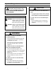
Important Safeguards This safety alert symbol identifies important safety messages in this manual. READ AND UNDERSTAND THEM BEFORE INSTALLING OR OPERATING THIS EQUIPMENT.
Important Safeguards (Continued) Important – In the event the following safety labels are damaged or destroyed, they must be replaced to ensure operator safety. See "Replacement Parts Illustrations and Parts Lists" for label part numbers.
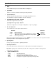
Specifications 1. Tape: For use with Scotch® pressure-sensitive film box sealing tapes. 2. Tape Width: 36 mm or 1-1/2 inches minimum to 48 mm [2 inches] maximum. 3. Tape Roll Diameter: Up to 405 mm [16 inches] maximum on a 76.2 mm [3 inch] diameter core. (Accommodates all system roll lengths of Scotch® film tapes.) 4.
Specifications (Continued) Figure 2-1 – Dimensional Drawing 5
Installation WARNING • To reduce the risk associated with sharp blade hazards: − Keep hands and fingers away from tape cutoff blades under orange blade guards. The blades are extremely sharp Receiving And Handling 3. Figure 2-1 illustrates the typical mounting relationship for opposing taping head assemblies to allow taping of box heights down to 90 mm [31/2 inches].
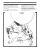
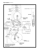
Operation Figure 3-1 – Taping Head Components/Threading Diagram, Upper Head (Left Side View) Figure 3-2 – Taping Head Components/Threading Diagram – Lower Head (Left Side View) 7
Operation (Continued) WARNING • To reduce the risk associated with shear, pinch, and entanglement hazards: − Turn air and electrical supplies off on associated equipment before performing any adjustments, maintenance, or servicing the machine or taping heads − Never attempt to work on the taping heads or load tape when the box drive system is running • To reduce the risk associated with sharp blade hazards: − Keep hands and fingers away from tape cutoff blades under orange blade guards.
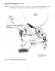
Operation (Continued) Figure 3-4 Place tape roll on tape drum to dispense tape with adhesive side forward. Seat tape roll fully against back flange of drum. Adhere tape lead end to threading needle as shown. Figure 3-4 – Tape Loading/Threading Figure 3-5 WARNING • To reduce the risk associated with sharp blade hazards: − Keep hands and fingers away from tape cutoff blades under orange blade guards.
Maintenance WARNING • To reduce the risk associated with shear, pinch, and entanglement hazards: − Turn air and electrical supplies off on associated equipment before performing any adjustments, maintenance, or servicing the taping heads − Never attempt to work on the taping head or load tape while the box drive system is running • To reduce the risk associated with sharp blade hazards: − Keep hands and fingers away from tape cutoff blades under orange blade guards.
Maintenance (Continued) WARNING • To reduce the risk associated with shear, pinch, and entanglement hazards: − Turn air and electrical supplies off on associated equipment before performing any adjustments, maintenance, or servicing the taping heads − Never attempt to work on the taping head or load tape while the box drive system is running • To reduce the risk associated with sharp blade hazards: − Keep hands and fingers away from tape cutoff blades under orange blade guards.
Adjustments WARNING • To reduce the risk associated with shear, pinch, and entanglement hazards: − Turn air and electrical supplies off on associated equipment before performing any adjustments, maintenance, or servicing the machine or taping heads − Never attempt to work on the taping head or load tape while the box drive system is running Figure 5-1 – Tape Latch Alignment Tape Latch Alignment – Figure 5-1 The Latching tape drum assembly is pre-set to accommodate 48 mm [2 inch] wide tape.
Adjustments (Continued) WARNING • To reduce the risk associated with shear, pinch, and entanglement hazards: − Turn air and electrical supplies off on associated equipment before performing any adjustments, maintenance, or servicing the machine or taping heads − Never attempt to work on the taping head or load tape while the box drive system is running Applying Mechanism Spring To obtain access to the spring, remove the taping head cover (four mounting screws). Replace cover when finished.
Adjustments (Continued)| WARNING • To reduce the risk associated with shear, pinch, and entanglement hazards: − Turn air and electrical supplies off on associated equipment before performing any adjustments, maintenance, or servicing the machine or taping heads − Never attempt to work on the taping head or load tape while the box drive system is running Tape Leg Length WARNING • To reduce the risk associated with sharp blade hazards: − Keep hands and fingers away from tape cutoff knives under orange bl
Troubleshooting Troubleshooting Guide Problem Cause Correction The tape leg on the front of the case is too long The tape is threaded incorrectly The tape must go around the wrap roller before going around the one-way tension roller The tape tension is too low Adjust the one-way tension roller The knurled roller drags Check for adhesive build-up between the knurled roller and its shaft. Clean and lubricate shaft. Remove all lubricant from roller surfaces.
Troubleshooting (Continued) Troubleshooting Guide Problem Cause Correction Tape is tabbing on the trailing leg on the back of the box There is excess tension on the tape drum assembly and/or the one-way tension roller assembly Adjust the one-way tension roller and/or the tape drum assembly Rollers in the tape path do not rotate freely Clean adhesive deposits from the surface, ends, and shafts of the rollers. Then lubricate roller shafts. Remove all lubricant from roller surfaces.
Spare Parts/Service Information Recommended Spare Parts A set of spare parts that will periodically require replacement due to normal wear is supplied with the taping heads. The set includes the following which should be reordered when used to keep the taping heads in production: AccuGlide™ 2+ STD 2 Inch Upper Taping Head Qty. Ref. No.
Replacement Parts Illustrations and Parts Lists AccuGlide™ 2+ STD 2 Inch Upper Taping Head, Type 10500 AccuGlide™ 2+ STD 2 Inch Lower Taping Head, Type 10500 1. Refer to the Taping Head Assemblies Figure to find all the parts illustrations identified by figure numbers. 2. Refer to the figure or figures to determine the individual parts required and the parts reference number. 3.
Taping Head Assemblies – AccuGlide™ 2+ STD 2 Inch 19
Figure 10397 – Upper Head 20
Figure 10397 – 2" Upper Head Ref. No. 3M Part No.
Figure 10393 – Upper and Lower Heads 22
Figure 10393 – 2" Upper and Lower Heads Ref. No. 3M Part No.
Figure 10387 – Upper Head 24
Figure 10387 – 2" Upper Head Ref. No. 3M Part No.
Figure 10395 – Upper and Lower Heads 26
Figure 10395 – 2" Upper and Lower Heads Ref. No. 3M Part No.
Figure 10391 – Upper and Lower Heads 28
Figure 10391 – 2" Upper and Lower Heads Ref. No. 3M Part No. Description 10391-1 78-8070-1217-0 Frame – Cut-Off Weldment 10391-2 78-8017-9173-8 Blade – 65 mm/2.
4 14 Figure 10401 – Upper and Lower Heads 30
Figure 10401 – 2" Latch Upper and Lower Heads Ref. No. 3M Part No.
Figure 10399 – Lower Head 32
Figure 10399 – 2" Lower Head Ref. No. 3M Part No.
Figure 10389 – Lower Head 34
Figure 10389 – Lower Head Ref. No. 3M Part No.