
User's Manual


Octopus ATM Defense System
Installation and Operation Guide
Page 9 of 25
Monitor and Control Unit (MCU)
The MCU is the monitor and control unit. It has 8 selectable sensor inputs for monitoring ATM status. The sensor
inputs contain normally-open (NO), normally-closed (NC), and an optical isolated inputs. The MCU also contains
on-board sensors for tilt, continuous motion, light sensor(s), and thermal violation. Details about the inputs may
be found in section 2.0 Installation Guides and in section 4.0 Functional Operation.
The external sensor inputs are accessed either through a RJ45 style connector or by direct interface into terminal
block on the PCB. As with the CSU a user accessible self-test button is provided for troubleshooting and
installation. On the MCU printed circuit board there are several jumper blocks present to enable/ disable certain
functionality.
Outputs include two RJ11 remote interface monitors and a terminal block for the optional smoke generator.
Internal to the unit is an RJ11 connector for future expansion of the system to allow remote communications.
Basic MCU installation is made by wiring in external sensors, configuring the unit functionality via the on-board
jumpers, and mounting the MCU inside the ATM safe.
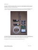
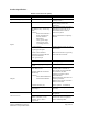
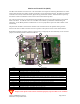
Bubble Identification
1 Terminal Block, left to right, NC Input 2, GND, Power, Breach, Door, GND
2 (RJ45) RJ45, 8 pin terminal for attachment of the sensor array cable. See Appendix C.
3 Programming header, no field usage at his time.
4 LED indicators
5 Buzzer
6 Press to test button (self-test)
7
Configuration jumpers, top to bottom, Unused, Unused, Enable Motion, Orientation Select, Squib Enable,
Enable Light Sensor. (See Appendix D for Proper Configuration)
8 Power jumper
9 Custom battery pack, with dual output and 3 pin locking plug for mating with “C” below.
A (RJ11 x2) Remote indication dry contact outputs for Fault, Alarm, and Fire status detection.
B Squib output terminal block for use with optional MCU smoke generator.
C Battery pack connector, 3 pin locking header for mating with “9” above.
D RS-232 interface (RJ11) - not populated and not currently in use.
E External Power Input – not populate and not currently in use
Table 3. MCU layout explanation.
All input Level specific sensors must be terminated properly to prevent MCU error conditions.
1
4
5
6
8
9
A
B
C
E
2
3
7
D