
User's Manual


Octopus ATM Defense System
Installation and Operation Guide
Page 6 of 25
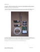
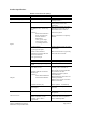
Product Specification:
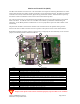
Monitor and Control Unit (MCU)
Description Specification Comments
Size: 3.3 x 5.6x 1.25 “
Operational Frequency: International Acceptance Frequency is not given for
security reasons.
Press-to-test button User accessible allows system
testing during service and
installation.
One RJ45, 8 wire, sensor array
cable
Contains:
Door Contact Interface
Power Loss Interface
All Safe Interface
Manual Fire
1 N/C generic input
2 N/O generic input
1 system ground wire
Door Contact must be used either
through the sensor cable or via
the terminal block in order to
activate the system.
Power Loss Interface is optically
isolated.
Terminal Blocks:
2 system ground inputs
1 Door Contact Interface
1 Manual Fire Interface/Breach
Power Loss Interface
1 N/C generic input
Terminal blocks accept wire from
18-24 AWG.
Manual Fire Interface is generally
used with a breach sensor.
Battery Pack connector
External Power Connector Currently not populated
Inputs:
14 Pin factory programming
header
Not for customer use
Three RJ11, 4 wire
2 Remote Indicator connectors
(J14 & J15)
Contains:
Alarm Status Indication
Fault Status Indication
1 RS232 Interface (J2)
An optional remote indicator
assembly will be available to
allow visual and aural indication
of system state to allow
authorized personnel system
status indication.
Remote Indicator connections are
mutually redundant.
Optional siren may be connected
to these connectors.
(Future options - not installed)
Outputs
Squib output
For connection to optional smoke
generator.
4 LED indicators
See Appendix A for explanation
of operation.
Onboard Sensors
Tilt 50° , 2 axis
Motion / Vibration, 2 axis.
Thermal –50 to +150 °C
Light Sensor
Operation using the light sensor
and thermal sensor are optional
on the standard product.