
User's Manual


Octopus ATM Defense System
Installation and Operation Guide
Page 8 of 25
Components Overview:
Cassette Staining Unit (CSU)
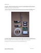
The CSUs are a complete self-contained staining system. The CSU has a custom battery pack, a vacuum form
cover, an electronics assembly, a mounting bracket, an ink reservoir, and an ink delivery system.
The electronics assembly (EAS) is generic and exists in all system installations; however, the ink reservoir,
bracket, and ink delivery system are specific to the manufacturer and model of the cassette. Further, positioning of
the ink spray bar is specific to the type of currency to be protected. A user accessible self-test button is provided
for system troubleshooting and periodic battery and maintenance testing.
Basic system configuration is an EAS attached to a bracket that holds the ink reservoir and the ink delivery
system. The EAS is attached with a squib wire to the ink reservoir for activation of the staining process. No other
physical connections are interfaced with the CSU.
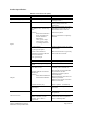
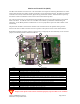
Bubble Identification/Explanation
1 Power On Self Test Button SW9. When activated the unit will perform a built in self test. If no errors or faults
present the unit will beep 1 time. If the unit beeps twice, there is an error.
2 Horizontal/Vertical jumper J11. When jumper is on, the unit expects to be orientated with component side
down. When the jumper is removed (as shown) the unit expects to be orientated vertically with the POST
button on top.
3 Disable Light Jumper J13. When the jumper is on, the unit will detect light. When off, the presence of light
will be ignored.
4 Squib wire for connection of electronic assembly to the ink delivery system.
5 Disable Squib jumper, J3. When installed allows proper operation. When removed renders the unit unable to
activate the ink delivery system.
6 Battery pack connector J12.
7 Power Jumper. Installation or removal of this jumper controls power to the unit.
8 Battery Pack.
Table 2. CSU layout explanation.
Both the SQUIB Jumper J3 and the ink delivery unit must be connected for the system to work
properly. The CSU will give an error message if either of these two items is not installed correctly.
4
6
5
7
8
1
2
3