Certification Exhibit FCC ID: Q6K-MCU102A IC: 5043A-MCU102A FCC Rule Part: 15.231 IC Radio Standards Specification: RSS-210 ACS Report Number: 10-0184.W06.11.A Manufacturer: 3Si Security Systems Model: MCU-102A Manual 5015 B.U.
Octopus Installation & User Manual Last Updated: 06/07/2010
Table of Contents How To Use This Guide ..................................................................................................... 3 FCC Statement .................................................................................................................... 3 Octopus System Description............................................................................................. 4 System Overview .................................................................................................
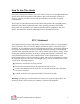
How To Use This Guide This guide is designed to introduce you to the features of the 3SI Octopus ATM Defense System and to assist in installation and operation. Due to the numerous variations in currency cassettes, procedures for the cassette installation are provided in separate documentation. The section on system description includes a brief background of the Octopus system, definition of the various operational states, daily operating procedures and system maintenance.
Octopus System Description System Overview The 3SI Octopus ATM Defense System is a patented wireless system designed to protect automatic teller machines (ATMs) from theft (pull-out) and break-in attacks. The system is comprised of three main components: a Monitor and Control Unit (MCU), up to 6 Cassette Staining Units (CSU), and an iButton Key Reader. The MCU is located in the main ATM safe area, and monitors the ATM for theft or break-in.
Enabled State – LED Green The Enabled state is applicable only to an Octopus system operating in the Door-Bolt mode. When both the door and door dead-bolt have been properly opened, the iButton LED will turn green indicating that the system is enabled but not armed. The system proceeds to the armed state (see below) when both the door and door dead-bolt are properly closed. Arming Delay (or “Pre-Armed”) State – LED Flash Red / Green Prior to arming there is a delay called the ―Arming Delay‖.
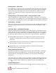
Octopus Components The Octopus system has 3 major components: the Monitor and Control Unit (MCU), the Cassette Staining Units (CSU), and the iButton reader. Monitor and Control Unit (MCU) The Monitor and Control Unit (MCU) is mounted inside the ATM safe. The purpose of the MCU is to monitor the status of the system and to control the activation of the Cassette Staining Units (CSU) and other optional features. The MCU is enabled or disabled using an I-Button Key (see iButton description below).
Power Supply & Backup Battery The MCU is powered by a UL approved plug-in 6 VDC power supply (1Amp minimum rating). It also has a back-up battery to maintain power in the event of an ATM power loss. The battery will provide backup power for approximately 3 weeks. Self Test Button On initial power up the MCU performs a self test routine. The MCU is also provided with a Push-To-Test (PTT) button which causes the unit to perform a self diagnostic test. If the test returns no errors, the MCU will beep 1 time.
Connector (iButton) The iButton Connector is a locking, polarized 10-pin connector. This connector is used to attach the cable from the iButton reader to the MCU. (Refer to the iButton reader description below) Relay Output Connection The MCU has two RJ11 output jacks which provide relay interface to the optional accessories such as: Internal Siren; Bank Alarm Interface; ATM Note-Stop. Both jacks are identical in function and pin-out. (Refer to Installation Procedures for wiring details.
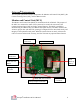
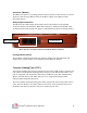
Spray Bar Bracket Ink Block Electronics CSU Installed in Cassette Ink Block Connector PTT (Service Only) Battery CSU Electronics Octopus Installation & User Manual 9
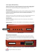
iButton Reader The iButton reader is used to enable and disable the Octopus system via the iButton Key. The iButton DB-9 serial interface connector provides a computer interface for initial system setup, and for retrieval of the system event log. The iButton Reader is mounted outside of the actual ATM safe, but inside the ATM enclosure in an area that is readily accessible during service. The iButton Reader is wired to the MCU via a multi-conductor cable.
Appendix A – Preparing for Installation Each installation has its own special requirements depending on the system configuration and options selected.
Field Logistics / Responsibilities: Personnel Involved Supplier Project Manager Responsibility Customer Project Manager Installer CIT (cash replenishing) Company ATM Technician Customer representative Develop the installation schedule with the Customer Project Manager Provide installation reports upon request Coordinate policy decisions relating to the responsibilities of the supplier Maintain channel of communication with the Customer Pro
Appendix B – Installation Report Date: ___/___/___ Initial Time: ___:___ Finished Time: ___:___ Customer: Location: ATM Make/Model: ATM Serial No: MCU Serial No: Check Point iButton Reader AC Power & Batteries Installed Breach Panel: quantity and location Taperwire: quantity and location Internal Siren Installed Door Switch Bolt Switch Installed Configuration & Mode Set MCU PTT OK MCU HyperTerminal Test OK Arming/Disarming Key Test OK Note-Stop installed / tested OK Bank Alarm Interface Installed CSU q
Appendix C – Installation Procedures 1. Determine where all system components are to be mounted: Refer to specific mounting requirements defined below. In particular the location of the MCU must be defined so that routing of all wiring can be planned. 2. Install any optional features: Refer to the Installation of Optional Features section below 3. Install Plug-In Power Supply: Plug the Power Supply into an available 120 VAC Power Strip within the ATM safe.
Mounting Notes: a) The door switch should be mounted away from the hinge side and cause no obstruction to the service or operation of the machine. b) Clean the surface where it will be mounted with the alcohol pad provided c) Mount the door switch ¾ inch back from the closed face of the door when shut. d) The door switch plunger should not impact the door where an item that moves, slides, or might otherwise cause a shearing action to the plunger.
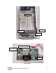
iButton Reader Mount the iButton Reader module in a place that is easy to access and highly visible to any ATM service technicians. It should be located inside the lockable outer ATM cabinet for security, but outside of the ATM safe. Route the iButton cable to the MCU location. LED Serial Port iButton Reader Mounting MCU Mount the MCU using hook-and-latch mounting tape, and attach all wiring.
ATM Warning Labels Two sets of warning labels are provided for each ATM installation. The external label is applied to the ATM exterior, and indicates to ATM users that the ATM is protected with the Octopus ATM Defense System. The internal labels are applied to the interior of the ATM cabinet and on all Cassettes, and indicate to maintenance personnel that an Octopus System is installed.
Appendix D – Managing iButton Keys The Octopus system uses 3 distinct iButton keys: a blue iButton key, a black iButton key, and a white iButton key. The system is shipped with 2 blue iButton keys configured to work only with the supplied MCU. The blue iButton keys are used for turning the system on and off. The black and white iButton keys are used only by 3SI service personnel for key management and replacement. Up to 3 blue keys can be stored / registered in the MCU.
Appendix E – Serial Communications Access If the system is Disabled (iButton LED off), serial communications can be established with the MCU. Any ASCII serial communication tool can be connected. Communication parameters are 9600 baud, 1 stop bit, no flow control. The serial interface provides: Retrieval of the internal system event log. Ability to enable a system without a preconfigured iButton Key. Ability to upgrade the system firmware without system removal.
3. When prompted with the Connect To box, go to ―Connect Using‖ and choose COM1. This tells the computer which hardware interface to use. COM1 is the standard. 4. After choosing COM1, click Ok.
5. When prompted with the Port Settings box, enter the following information, then click OK: Bits per second: 9600 Data bits: 8 Parity: None Stop bits: 1 Flow control: None 6. Successful communication is indicated in the bottom left-hand corner of the screen where it will say ―Connected‖, followed by the elapsed time of the connection.
7. Go to File > Properties, choose the Settings tab, then click the ASCII Setup button.
8. In the ASCII Setup box, change the following: Check ―Send line ends with line feeds‖ Change the Line Delay to 1 millisecond Click Ok. 9. Click Ok on Settings to close the window. 10. Close the HyperTerminal window. You will get a dialogue box asking if you are sure you want to disconnect. Click Yes. 11. You will get a dialogue box that asks if you want to save session. Click Yes.
After saving the HyperTerminal connection ―Octopus‖, the connection will always be in HyperTerminal folder. To save it on the desktop for easy future access, right click on the file and choose Send to > Desktop (create shortcut). An icon will appear on the desktop.
Accessing Serial Communications and Using the Menu To initiate serial communications with the Octopus system, follow these instructions. Note: The Octopus system can only communicate with a computer when the system is in the Disabled State. If the system is Armed, it must first be turned off with a blue iButton key. 1. Plug in an RS232 cable to the mating RS232 connector on the Octopus iButton reader. 2.
4. Press spacebar to access the main menu which will look like this: 5. If no key is pressed for 1 minute, you will receive the PC Communication Timeout screen. Press spacebar again to return to main menu.
Navigating the Main Menu (Note: Caps lock must be ON) 1. Turn Unit On a) Press 1 on the keyboard b) You will receive the following warning screen because you can only turn the unit ON with serial communications—if you do not have a blue iButton key, you cannot turn the system OFF once it is On. c) After you type ―Y,‖ the unit is on but won’t go into Armed state yet. You must exit this menu by pressing ―Y,‖ then type ―6‖ to exit the main menu.
2. Capture Text File and Read Log Note: Before you choose Read Log, you must first capture the session to text file. That way, if there is a problem you want to report, you have a copy of the session to send to 3SI. a) At the top of the window, Choose Transfer > Capture text. b) Browse to the folder where you want to save text file by clicking Browse.
c) Name the file Octopus_‖date‖ and click Save. Then click Start. d) After you save the text file, type ―2‖ to read the log: Serial # of each key. If all 0s, any 3SI key will work. Cause of last activation. Cause of last Arming. Cause of last Disarming. Last 16 events. Next 14 are on following page (press Y to continue).
The log readout shows the last 30 events, date, time (in GMT), what the event was, what state the unit was in, and the status of dip-switches (whether dip-switches were on or off). The 30 events are provided on two pages: 16 events on the first page, 14 events on second page. To continue and access the second page, type ―Y‖. 3. Update Firmware Update Firmware should not be accessed without first contacting 3SI.
4. Run Self-Test Typing ―4‖ to run the self-test will produce the following screen: Each line provides system status information: System Time: Provides current time in GMT with a real-time clock. Last iButton: Provides the serial number of the last iButton Key used. If, during selftest you key an iButton, the screen will provide the serial number and color of the button. Use this to verify that the iButton Key is valid.
Charge Current: Shows whether the battery is being charged. If the number is greater than 100 mA, the unit is being charged. External Power: Shows whether external power is present or not. Door-Bolt Mode: Shows whether Door-Bolt Mode is selected or not. Time Left: Shows the self-test time remaining. Self test will run continuously for 5 minutes (300 seconds) or until a key is pressed to exit. 5.
Appendix F – Optional Features Bank Alarm Interface The Bank Alarm Interface feature enables the MCU to notify the bank’s alarm system that the ATM has been attacked. A set of normally closed (NC) contacts are provided for this purpose. Connection is made via either J14 or J15 using a standard RJ-11 connector. Internal Siren Module The Internal Siren Module is a self-powered 128 dB audio siren. The siren will alert onlookers and possible witnesses that the ATM has been attacked.
Mesh Panel Taperwire The Taperwire is an adhesive-backed flat wire. Its purpose is to provide spot protection for along the ATM safe walls. The customer should provide details as to the most likely methods of attack and desired protection areas.
Note-Stop The Note-Stop option adds the capability to shut down the ATM in the event of an attack (so that it will not dispense money). Installation of the Note-Stop requires interruption of the ATM internal power, and requires coordination with the ATM manufacturer.