
User Manual
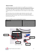
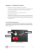
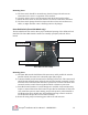
Table Of Contents

Octopus Installation & User Manual – APPENDIX C
C1
Appendix C – Installation Procedures
1. Determine where all system components are to be mounted:
Refer to specific mounting requirements defined below. In particular the location
of the MCU must be defined so that routing of all wiring can be planned.
2. Install any optional features:
Refer to the Installation of Optional Features section below
3. Install Plug-In Power Supply:
Plug the Power Supply into an available 120 VAC Power Strip within the ATM
safe. Route the low voltage wiring (with connector) to the planned MCU location.
4. Install Door and Door-Bolt Switches (as required), and other system components
as described below:
Door Switch (Door-Bolt Mode only)
The Door Switch is a long throw-plunger switch. Its purpose is to detect the ATM safe
door position (open / closed) The Door Switch is supplied with a mounting frame with
permanent adhesive mounting tape. The Door Switch contacts are normally closed (NC)
when the door is closed.
Door Switch
Mounting Frame
Door Switch Assembly
Crimp Connectors