
User Manual
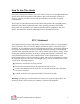
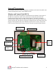
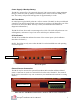
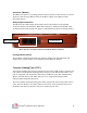
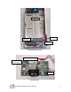
Table Of Contents

Octopus Installation & User Manual
7
Power Supply & Backup Battery
The MCU is powered by a UL approved plug-in 6 VDC power supply (1Amp minimum
rating). It also has a back-up battery to maintain power in the event of an ATM power
loss. The battery will provide backup power for approximately 3 weeks.
Self Test Button
On initial power up the MCU performs a self test routine. The MCU is also provided with
a Push-To-Test (PTT) button which causes the unit to perform a self diagnostic test. If the
test returns no errors, the MCU will beep 1 time. (See Installation Procedures for
diagnostics information.)
The MCU self test also sends a test message to the CSUs. The CSU will perform its own
self diagnostic, and return 1 beep for no error and 2 beeps to indicate an error.
LED Indicators
The MCU has 4 LEDs that indicate the status of the various inputs. (See Installation
Procedures for details.)
NOTE: The LEDs are only active when the MCU is in the Disabled state and operating
on external power.
External Sensor Connection
The MCU may be connected to optional Door/Door-Bolt switches and Breach Panel
sensor. Connection is made via a terminal block on the side of the MCU. The terminal
block may be removed for easy wire connection. (See Installation Procedures for wiring
details.)
MCU front panel
MCU side view with iButton/serial interface connector and ext sensor terminal block
LED Indicators
PTT Button
iButton Connector
Ext Sensor Connector