
User Manual
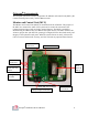
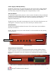
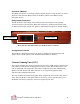
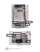
Table Of Contents

Octopus Installation & User Manual
8
Connector (iButton)
The iButton Connector is a locking, polarized 10-pin connector. This connector is used to
attach the cable from the iButton reader to the MCU. (Refer to the iButton reader
description below)
Relay Output Connection
The MCU has two RJ11 output jacks which provide relay interface to the optional
accessories such as: Internal Siren; Bank Alarm Interface; ATM Note-Stop. Both jacks
are identical in function and pin-out. (Refer to Installation Procedures for wiring details.)
Configuration Switches
The 10 MCU Configuration Switches are used to configure the operating mode and
options for the system. (Refer to the Installation Procedures for details.)
Cassette Staining Unit (CSU)
The Cassette Staining Unit (CSU) is mounted in each of the ATM currency cassettes. The
CSU utilizes a small profile mounting bracket unique to each make/model cassette. The
CSU is comprised of 4 components: Electronics, Ink Block, Spray Bar, and Mounting
Bracket. The link between the MCU and CSU is via a proprietary patented radio
frequency (RF) communications link.
The CSU contains an internal battery pack which will provide power to the CSU for two
years. The CSU Push-To-Test (PTT) button is for use by service personnel only. Once
installed in the currency cassettes, no action is required by the user.
MCU side view with RJ11 connectors and 6VDC Power Connector
Relay Connectors
6VDC Power