
Datasheet


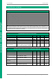

4D SYSTEMS uLCD-144G2
© 2014 4D SYSTEMS Page 12 of 18 www.4dsystems.com.au
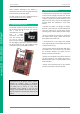
microLCD GOLDELOX DISPLAY
Workshop 4 – Designer Environment 10.1.
Choose the Designer environment to write 4DGL
code in its raw form.
The Designer environment provides the user with
a simple yet effective programming environment
where pure 4DGL code can be written, compiled
and downloaded to the Module.
Workshop 4 – ViSi Environment 10.2.
ViSi was designed to make the creation of
graphical displays a more visual experience.
ViSi is a great software tool that allows the user to
see the instant results of their desired graphical
layout. Additionally, there is a selection of inbuilt
dials, gauges and meters that can simply be placed
onto the simulated module display. From here
each object can have its properties edited, and at
the click of a button all relevant 4DGL code
associated with that object is produced in the user
program. The user can then write 4DGL code
around these objects to utilise them in the way
they choose.
Workshop 4 – Serial Environment 10.3.
The Serial environment in the Workshop 4 IDE
provides the user the ability to transform the
Module into a slave serial graphics controller.
This enables the user to use their favourite
microcontroller or serial device as the Host,
without having to learn 4DGL or program in a
separate IDE. Once the Module is configured and
downloaded to from the Serial Environment,
simple graphic commands can be sent from the
users host microcontroller to display primitives,
images, sound or even video.
Refer to the “Serial Command Set Reference
Manual” from the Workshop 4 product page on
the 4D Systems website for a complete listing of all
the supported serial commands
By default, each module shipped from the 4D
Systems factory will come pre-programmed ready
for use in the Serial mode.