WM-MB92M Mini PCI Module
Product Handbook WM-MB92M ENGLISH Copyright Notice This document is protected by USA copyright laws and other laws. Besides, the document is the property of 4IPNET, INC. You may not copy, reproduce, distribute, publish, display, perform, or modify any part of this publication in any form or by any means without prior written permission from 4IPNET, INC. You may not alter or remove any copyright or other notice from copies of the content.
Product Handbook WM-MB92M ENGLISH FCC CAUTION This device complies with Part 15 of the FCC Rules. Operation is subject to the following two conditions: (1) This device may not cause harmful interference, and (2) this device must accept any interference received, including interference that may cause undesired operation. This equipment has been tested and proven to comply with the limits for a class B digital device, pursuant to part 15 of the FCC Rules.
Product Handbook WM-MB92M ENGLISH integrator is still responsible for testing their end-product for any additional compliance requirements required with this module installed IMPORTANT NOTE: In the event that these conditions can not be met (for example certain laptop configurations or co-location with another transmitter), then the FCC authorization is no longer considered valid and the FCC ID can not be used on the final product.
Product Handbook WM-MB92M ENGLISH CE CAUTION Declaration of Conformity with Regard to the 1999/5/EC (R&TTE Directive) for European Community, Switzerland, Norway, Iceland, and Liechtenstein Model: WM-MB92M For 2.4 GHz radios, the device has been tested and passed the requirements of the following standards, and hence fulfills the EMC and safety requirements of R&TTE Directive within the CE marking requirement. • Radio: EN 300.328: • EMC: EN 301.489-1, EN 301.
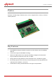
Product Handbook WM-MB92M ENGLISH Preface The WM-MB92M 802.11a/b/g/n MMCX Mini PCI Module is compliant with IEEE 802.11a standards and 802.11b/g/n standards, which can be integrated with a variety of wireless network platforms. Key Features Fully IEEE 802.11a/b/g/n standards compliant to provide wireless speed of 300Mbps data rate. 2 antennas to support 2T2R MIMO technology.
Product Handbook WM-MB92M ENGLISH WM-MB92M 802.11 a/b/g/n MMCX Mini PCI Module Specifications: Chipset Atheros (AR9220) Interface Type Mini PCI Type III A IEEE 802.11a 4 Channels / 5150MHz – 5250MHz (Japan) 19 Channels / 5150MHz – 5350MHz / 5470MHz – 5725MHz (Europe) Channel and Frequency 13 Channels / 5150MHz – 5250MHz / 5725MHz – 5850MHz (USA) 13 Channels / 5250MHz – 5350MHz / 5725MHz – 5850MHz (Taiwan) IEEE 802.11b/g/n 14 Channels (Japan) 13 Channels (Europe) 11 Channels (USA) / 2400MHz – 2483.
Product Handbook WM-MB92M ENGLISH Data Modulation Type 802.11a: 64QAM, 16QAM, QPSK, BPSK 802.11b: DBPSK, DQPSK, CCK 802.11g: BPSK, QPSK, 16QAM, 64QAM 802.11n: 64QAM, 16QAM, QPSK, BPSK Operating Voltage 3.3 Volt + 5% Power Consumption TX : Under 800mA RX : Under 350mA Antenna Connector 2 x MMCX connectors Security 64/128/152-bits WEP, WPA, WPA2, Encryption TKIP / AES, 802.
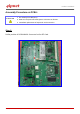
Product Handbook WM-MB92M ENGLISH Assembly Procedure on PCBA: ATTENTION 1. No stacking of PCBA (DUT). 2. ESD wrist strip and anti-static gloves to be worn at all times 3. Immediate replacement of inept tools and accessories Step 1: Define position of PCBA MMCX Connector for first RF Card. 2 1 Copyright © 4IPNET, INC. All rights reserved.
Product Handbook WM-MB92M ENGLISH Step 2: Adhere FPC Antenna on inner side of top lid and attach connectors to the defined PCBA position for the first RF Card. 1 2 2 1 Copyright © 4IPNET, INC. All rights reserved.
Product Handbook WM-MB92M ENGLISH Step 3: Place PCBA in enclosure with the first RF Card facing down Copyright © 4IPNET, INC. All rights reserved.
Product Handbook WM-MB92M ENGLISH Step 4: Tighten the 4 screws on PCBA as marked in the stated order. Make sure the RJ45 ports are aligned to the enclosure. 1 3 Copyright © 4IPNET, INC. All rights reserved.
Product Handbook WM-MB92M ENGLISH Step 5: Adhere FPC Antenna on inner side of top lid and attach connectors to the defined PCBA position for the second RF Card. 2 1 1 Copyright © 4IPNET, INC. All rights reserved.
Product Handbook WM-MB92M ENGLISH Step 6: Insert Antenna cable into the highlighted area. Copyright © 4IPNET, INC. All rights reserved.
Product Handbook WM-MB92M ENGLISH Step 7: Close the enclosure and ensure that the antenna cables are not pressed in between the lid and the enclosure. Copyright © 4IPNET, INC. All rights reserved.
Product Handbook WM-MB92M ENGLISH Step 8: Tighten the 4 screws for the enclosure in the stated order to complete the assembly procedure. 1 3 2 4 The device label of the product shall include the NCC ID of assembled RF NOTE: module. 平 台 業 者 於 安 裝 此 模 組 至 系 統 設 備 時 需 標 示 「 內 含 發 射 器 模 組 : 」 P/N: V10020140210 Copyright © 4IPNET, INC. All rights reserved.