July 2015 Version 1.5.
| 1 Copyright Copyright © 2015 4RF Limited. All rights reserved. This document is protected by copyright belonging to 4RF Limited and may not be reproduced or republished in whole or part in any form without the prior written permission of 4RF Limited. Trademarks Aprisa and the 4RF logo are trademarks of 4RF Limited. Windows is a registered trademark of Microsoft Corporation in the United States and other countries.
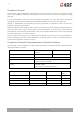
2 | Compliance General The Aprisa SR+ radio predominantly operates within frequency bands that require a site license be issued by the radio regulatory authority with jurisdiction over the territory in which the equipment is being operated. It is the responsibility of the user, before operating the equipment, to ensure that where required the appropriate license has been granted and all conditions attendant to that license have been met.
| 3 Compliance Federal Communications Commission The Aprisa SR+ radio is designed to comply with the Federal Communications Commission (FCC) specifications as follows: Radio 47CFR part 24, part 90 and part 101 Private Land Mobile Radio Services EMC 47CFR part 15 Radio Frequency Devices, EN 301 489 Parts 1&4 Environmental EN 300 019, Class 3.
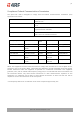
4 | Compliance Industry Canada The Aprisa SR+ radio is designed to comply with Industry Canada (IC) specifications as follows: Radio RSS-119 / RSS-134 EMC This Class A digital apparatus complies with Canadian standard ICES-003. Cet appareil numérique de la classe A est conforme à la norme NMB-003 du Canada. Environmental EN 300 019, Class 3.
| 5 Compliance Hazardous Locations Notice This product is suitable for use in Class 1, Division 2, Groups A - D hazardous locations or non-hazardous locations. The following text is printed on the Aprisa SR+ fascia: WARNING: EXPLOSION HAZARD - Do not connect or disconnect while circuits are live unless area is known to be non-hazardous.
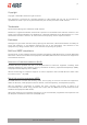
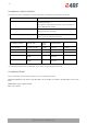
6 | RF Exposure Warning WARNING: The installer and / or user of Aprisa SR+ radios shall ensure that a separation distance as given in the following table is maintained between the main axis of the terminal’s antenna and the body of the user or nearby persons. Minimum separation distances given are based on the maximum values of the following methodologies: 1. Maximum Permissible Exposure non-occupational limit (B or general public) of 47 CFR 1.1310 and the methodology of FCC’s OST/OET Bulletin number 65.
Contents | 7 Contents 1. Introduction ............................................................................ 11 The 4RF Aprisa SR+ Radio ...................................................................... 11 Product Overview ............................................................................... 12 Network Coverage and Capacity ....................................................... 12 Automatic Registration ..................................................................
8 | Contents 3. Specifications .......................................................................... 38 RF Specifications ................................................................................ 38 Frequency Bands ......................................................................... 38 Channel Sizes ............................................................................. 39 Receiver ................................................................................... 44 Transmitter ...
Contents | ix 6. Product Architecture ................................................................. 67 Product Operation .............................................................................. 67 Physical Layer............................................................................. 67 Data Link Layer / MAC layer ............................................................ 67 Channel Access .................................................................... 67 Hop by Hop Transmission .....
Introduction | 11 1. Introduction The 4RF Aprisa SR+ Radio The 4RF Aprisa SR+ is a point-to-multipoint digital radio providing secure narrowband wireless data connectivity for SCADA, infrastructure and telemetry applications. The radios carry a combination of serial packet data and Ethernet data between the base station, repeater stations and remote stations. The Aprisa SR+ is configurable as a point-to-multipoint base station, a remote station or a repeater station. Aprisa SR+ Product Description 1.5.
12 | Introduction Product Overview Network Coverage and Capacity The Aprisa SR+ has a typical link range of up to 120 km, however, geographic features, such as hills, mountains, trees and foliage, or other path obstructions, such as buildings, will limit radio coverage. Additionally, geography may reduce network capacity at the edge of the network where errors may occur and require retransmission.
Introduction | 13 Store and Forward Repeater The Aprisa SR+ in Repeater mode is used to link remote stations to the base station when direct communication is not possible due to terrain, distance, fade margin or other obstructions in the network. The following example depicts a repeater on the hill top to allow communication between the base station and the remote stations on the other side of hilly terrain.
14 | Introduction Multiple Repeater Single Hop The following example depicts an Aprisa SR+ multiple repeater single hop store and forward network supporting both overlapping and non-overlapping coverage repeater networks. An overlapped RF coverage area creates radio interference and might affect network performance and reduce throughput, as show in figure (a), where Remote 1 is in overlapped RF coverage with Repeater 1 and Repeater 2. Aprisa SR+ Product Description 1.5.
Introduction | 15 Multiple Repeater Multiple Hop The following example depicts an Aprisa SR+ daisy chain multiple repeater multiple hop store and forward network i.e. multiple hops and multiple repeaters in non-overlapping RF coverage. The Aprisa SR+ daisy chain store and forward repeaters are currently supported in LBS MAC mode only.
16 | Introduction Repeater Messaging The Aprisa SR+ uses a routed protocol throughout the network whereby messages contain source and destination addresses. The remote and repeater stations will register with a base station. In networks with a repeater, the repeater must register with the base station before the remotes can register with the base station.
Introduction | 17 Product Features Functions Point-to-Point (PTP) or Point-to-Multipoint (PMP) operation Licensed frequency bands: VHF 135 135-175 MHz VHF 220 215-240 MHz UHF 320 320-400 MHz UHF 400 400-470 MHz UHF 450 450-520 MHz UHF 896 896-902 MHz UHF 928 928-960 MHz Channel sizes – software selectable: 12.
18 | Introduction Radio and user interface redundancy (provided with Aprisa SR+ Protected Station) Protected Station fully hot swappable and monitored hot standby Transparent to all common SCADA protocols; e.g. Modbus, IEC 60870-5-101/104, DNP3 or similar Complies with international standards, including ETSI, FCC, IC, ACMA, EMC, safety and environmental standards Security The Aprisa SR+ provides security features to implement the key recommendations for industrial control systems.
Introduction | 19 Performance Typical deployment of 30 remote stations from one base station with a practical limit of a few hundred remote stations Long distance operation High transmit power Low noise receiver Forward Error Correction Electronic tuning over the frequency band Thermal management for high power over a wide temperature range Usability Configuration / diagnostics via front panel Management Port USB interface, Ethernet interface Built-in webserver SuperVisor
20 | Introduction System Gain vs FEC Coding This table shows the relationship between modulation, FEC coding, system gain, capacity and coverage.
Introduction | 21 Architecture The Aprisa SR+ Architecture is based around a layered TCP/IP protocol stack: Physical Proprietary wireless RS-232 and Ethernet interfaces Link Proprietary wireless (channel access, ARQ, segmentation) VLAN aware Ethernet bridge Network Standard IP Proprietary automatic radio routing table population algorithm Transport TCP, UDP Application HTTPS web management access through base station with proprietary management application software including management o
22 | Introduction Interfaces Antenna Interface 2 x TNC, 50 ohm, female connectors Single or dual antenna ports (with or without the use of external duplexer/filter) Ethernet Interface 2, 3 or 4 ports 10/100 base-T Ethernet layer 2 switch using RJ45 Used for Ethernet user traffic and radio sub-network management.
Introduction | 23 Mounting The Aprisa SR+ has four threaded holes (M4) in the enclosure base and two holes (5.2 mm) through the enclosure for mounting.
24 | Introduction The Aprisa SR+ DIN rail mounting bracket can be mounted in four positions on a horizontal DIN rail: Vertical Mount (vertical enclosure perpendicular to the mount) Horizontal Mount (horizontal enclosure perpendicular to the mount) Flat Vertical Mount (vertical enclosure parallel to the mount) Flat Horizontal Mount (horizontal enclosure parallel to the mount) Aprisa SR+ Product Description 1.5.
Introduction | 25 Rack Shelf Mounting The Aprisa SR+ can be mounted on a rack mount shelf using the four M4 threaded holes in the Aprisa SR+ enclosure base. The following picture shows two Aprisa SR+ radios mounted on 1 RU rack mount shelf. Part Number Part Description APSB-MR19-X1U 4RF SR+ Acc, Mounting, 19" Rack Mount Shelf, 1U WARNING: If the Aprisa SR+ is operated in an environment where the ambient temperature exceeds 50°C, the Aprisa SR+ convection air flow over the heat sinks must be considered.
26 | Introduction Wall Mounting The Aprisa SR+ can be mounted on a wall using the two holes through the enclosure (5.2 mm diameter). Typically, M5 screws longer than 35 mm would be used. Aprisa SR+ Product Description 1.5.
Product Options | 27 2. Product Options Interface Ports The standard Aprisa SR+ provides multiple interface port options for combinations of Ethernet and RS-232 serial. The product shown below is the two Ethernet ports plus two RS-232 serial ports.
28 | Product Options Protected Station The Aprisa SR+ Protected Station is full monitored hot-standby and fully hot-swappable. The Aprisa SR+ Protected Station provides radio and user interface protection for Aprisa SR+ radios when configured as a base station. The RF ports and interface ports from the active Aprisa SR+ radio are switched to the standby radio if there is a failure in the active radio.
Product Options | 29 Operation In hot-standby normal operation, the active radio carries all RS-232 serial and Ethernet traffic over the radio link and the standby radio transmit is on with its transmitter connected to an internal load. Both radios are continually monitored for correct operation including the transmitter and receiver and alarms are raised if an event occurs. The active radio sends regular ‘keep alive’ messages to the standby radio to indicate it is operating correctly.
30 | Product Options Data Driven Protected Station The Aprisa SR+ Data Driven Protected Station provides radio and RS-232 serial port user interface protection for Aprisa SR+ radios.
Product Options | 31 Switch Over The active radio is determined explicitly by which radio receives data on its RS-232 serial port. The switching and blocking criteria used for the standard Protected Station do not apply. This means that events and alarms on the unit are not used as switching criteria. Configuration Management The Primary and Secondary radios are managed with the embedded web-based management tool, SuperVisor by using either the Primary or Secondary IP address.
32 | Product Options Duplexer Kits The Aprisa SR+ product range contains Duplexer Kit accessories for use with the Dual Antenna port Aprisa SR+ radios. Radio Duplexer Kits Example of part number: APSB-KDUP-928-G2-BR Part Number Description APSB-KDUP-135-N0-BR Aprisa SR+ Duplexer Kit for a SR+ Radio containing: 1x 1U 19" rack front mount shelf with duplexer mounting brackets and screws to mount 1x SR+ radio and 1x duplexer 1x N0 Duplexer 135 MHz, s4.6 MHz, p0.
Product Options | 33 Part Number Description APSB-KDUP-928-G0-BR Aprisa SR+ Duplexer Kit for a SR+ radio containing: 1x 1U 19" rack front mount shelf with duplexer mounting brackets and screws to mount 1x SR+ radio and 1x duplexer 1x G0 Duplexer 900 MHz, s 40 MHz, p 7 MHz 2x TNC to SMA right angle 640mm cables APSB-KDUP-928-G2-BR-MM Aprisa SR+ Duplexer Kit for a SR+ radio containing: 1x 1U 19" rack mid mount shelf with duplexer mounting brackets and screws to mount 1x SR+ radio and 1x duplexer 1x G2 D
34 | Product Options Protected Station Duplexer Kits Example of part number: APSB-KDUP-928-G2-PS Part Number Description APSB-KDUP-135-N0-PS Aprisa SR+ Duplexer Kit for a SR+ Protected Station containing: 1x N0 Duplexer 135 MHz, s4.6 MHz, p0.5 MHz 2x right angle TNC to SMA right angle 640mm cables Rack front mounted APSB-KDUP-135-N0-PS-DA Aprisa SR+ Duplexer Kit for a dual antenna SR+ Protected Station containing: 2x N0 Duplexer 135 MHz, s4.6 MHz, p0.
Product Options | 35 Part Number Description APSB-KDUP-400-B1-PS Aprisa SR+ Duplexer Kit for a SR+ Protected Station containing: 1x 1U 19" rack front mount shelf with duplexer mounting brackets and screws 1x B1 Duplexer 400 MHz, s 5 MHz, p 0.5 MHz 2x right angle TNC to SMA right angle 640mm cables APSB-KDUP-450-M0-PS Aprisa SR+ Duplexer Kit for a SR+ Protected Station containing: 1x 1U 19" rack front mount shelf with duplexer mounting brackets and screws 1x M0 Duplexer 450 MHz, s 5 MHz, p 0.
36 | Product Options Part Number Description APSB-KDUP-928-G3-PS Aprisa SR+ Duplexer Kit for a SR+ Protected Station containing: 1x 2U 19" rack front mount shelf with duplexer mounting brackets and screws 1x G3 Duplexer 900 MHz, s5.5 MHz, p0.5 MHz 2x TNC to SMA right angle 640mm cables Aprisa SR+ Product Description 1.5.
Product Options | 37 USB RS-232 / RS-485 Serial Port The Aprisa SR+ USB host port is predominantly used for software upgrade and diagnostic reporting. However, it can also be used to provide an additional RS-232 DCE or RS-485 serial port for customer traffic. This is accomplished with a USB to RS-232 / RS-485 serial converter cable. This plugs into the USB host port connector and can be terminated with the required customer connector.
38 | Specifications 3. Specifications RF Specifications Blocking (desensitization), intermodulation, spurious response rejection, and adjacent channel selectivity values determined according to the methods introduced in V1.7.1 of ETSI standards EN 300 113-1. Frequency Bands ETSI Compliant Broadcast Band Frequency Band Frequency Tuning Range Synthesizer Step Size UHF 320 MHz 320-400 MHz 6.
Specifications | 39 Channel Sizes ETSI Compliant 320 / 400 / 450 MHz Bands No Forward Error Correction Channel Size Gross Radio Capacity 64 QAM 16 QAM QPSK 4-CPFSK 12.5 kHz 60.0 kbit/s 40.0 kbit/s 20.0 kbit/s 9.6 kbit/s 20 kHz 84.0 kbit/s 56.0 kbit/s 28.0 kbit/s 9.6 kbit/s 25 kHz 120.0 kbit/s 80.0 kbit/s 40.0 kbit/s 19.2 kbit/s Minimum Coded Forward Error Correction Channel Size Gross Radio Capacity less FEC 64 QAM 16 QAM QPSK 4-CPFSK 12.5 kHz 52.0 kbit/s 23.1 kbit/s 11.
40 | Specifications 320 MHz Band in Austria No Forward Error Correction Channel Size Gross Radio Capacity 64 QAM 16 QAM QPSK 4-CPFSK 20 kHz 84.0 kbit/s 56.0 kbit/s 28.0 kbit/s 9.6 kbit/s 50 kHz 216.0 kbit/s 144.0 kbit/s 72.0 kbit/s 38.4 kbit/s Minimum Coded Forward Error Correction Channel Size Gross Radio Capacity less FEC 64 QAM 16 QAM QPSK 4-CPFSK 20 kHz 72.7 kbit/s 32.4 kbit/s 16.2 kbit/s 8.4 kbit/s 50 kHz 187.1 kbit/s 83.2 kbit/s 41.6 kbit/s 33.
Specifications | 41 FCC / IC Compliant 400 / 450 MHz Bands No Forward Error Correction Channel Size Gross Radio Capacity 64 QAM 16 QAM QPSK 4-CPFSK 12.5 kHz 54.0 kbit/s 36.0 kbit/s 18.0 kbit/s 9.6 kbit/s 25 kHz 96.0 kbit/s 64.0 kbit/s 32.0 kbit/s 19.2 kbit/s Minimum Coded Forward Error Correction Channel Size Gross Radio Capacity less FEC 64 QAM 16 QAM QPSK 4-CPFSK 12.5 kHz 46.8 kbit/s 20.8 kbit/s 10.4 kbit/s 8.4 kbit/s 25 kHz 83.1 kbit/s 37.0 kbit/s 18.5 kbit/s 16.
42 | Specifications 220 MHz Band No Forward Error Correction Channel Size Gross Radio Capacity 64 QAM 16 QAM QPSK 4-CPFSK 12.5 kHz 54.0 kbit/s 36.0 kbit/s 18.0 kbit/s 9.6 kbit/s 15 kHz 60.0 kbit/s 40.0 kbit/s 20.0 kbit/s 9.6 kbit/s 25 kHz 96.0 kbit/s 64.0 kbit/s 32.0 kbit/s 19.2 kbit/s 50 kHz 216.0 kbit/s 144.0 kbit/s 72.0 kbit/s 38.4 kbit/s Minimum Coded Forward Error Correction Channel Size Gross Radio Capacity less FEC 64 QAM 16 QAM QPSK 4-CPFSK 12.5 kHz 46.8 kbit/s 20.
Specifications | 43 896 / 928 MHz Bands No Forward Error Correction Channel Size Gross Radio Capacity 64 QAM 16 QAM QPSK 4-CPFSK 12.5 kHz 60.0 kbit/s 40.0 kbit/s 20.0 kbit/s 9.6 kbit/s 25 kHz 96.0 kbit/s 64.0 kbit/s 32.0 kbit/s 19.2 kbit/s 50 kHz 216.0 kbit/s 144.0 kbit/s 72.0 kbit/s 38.4 kbit/s Minimum Coded Forward Error Correction Channel Size Gross Radio Capacity less FEC 64 QAM 16 QAM QPSK 4-CPFSK 12.5 kHz 52.0 kbit/s 23.1 kbit/s 11.6 kbit/s 8.4 kbit/s 25 kHz 83.
44 | Specifications Receiver ETSI / FCC / IC Compliant Receiver Sensitivity 12.
Specifications | 45 ETSI / FCC / IC Compliant Adjacent Channel Selectivity Adjacent channel selectivity 12.5 kHz 25 kHz 50 kHz > -47 dBm > -37 dBm > -37 dBm BER < 10 -2 64 QAM > 43 dB > 53 dB > 53 dB BER < 10 -2 16 QAM > 43 dB > 53 dB > 53 dB QPSK > 48 dB > 58 dB > 58 dB 4-CPFSK > 55 dB > 65 dB > 65 dB 12.
46 | Specifications ETSI / FCC / IC Compliant Spurious Response Rejection Spurious response rejection 12.5 kHz 25 kHz 50 kHz > -32 dBm > -32 dBm > -32 dBm -2 64 QAM > 58 dB > 58 dB > 58 dB BER < 10-2 16 QAM > 58 dB > 58 dB > 58 dB QPSK > 63 dB > 63 dB > 63 dB 4-CPFSK > 70 dB > 70 dB > 70 dB 12.
Specifications | 47 Transmitter Average Power output 64 QAM 0.01 to 2.5 W (+10 to +34 dBm, in 1 dB steps) Note: The Peak Envelope Power (PEP) at maximum set power level is +41 dBm. 16 QAM 0.01 to 3.2 W (+10 to +35 dBm, in 1 dB steps) QPSK 4-CPFSK 0.01 to 5.0 W (+10 to +37 dBm, in 1 dB steps) (Note 1) 0.01 to 10.
48 | Specifications Interface Specifications Ethernet Interface The Aprisa SR+ radio features an integrated 10Base-T/100Base-TX layer-2 Ethernet switch. To simplify network setup, each port supports auto-negotiation and auto-sensing MDI/MDIX. Operators can select from the following preset modes: Auto negotiate 10Base-T half or full duplex 100Base-TX half or full duplex The Ethernet ports are IEEE 802.3-compatible. The L2 Bridge (Switch) is IEEE 802.
Specifications | 49 RS-232 Asynchronous Interface The Aprisa SR+ radio’s ITU-T V.24 compliant RS-232 interface is configured as a Cisco® pinout DCE. The interface terminates to a DTE using a straight-through cable or to a DCE with a crossover cable (null modem). The interface uses two handshaking control lines between the DTE and the DCE. General Interface ITU-T V.
50 | Specifications Hardware Alarms Interface The hardware alarms interface supports two alarm inputs and two alarms outputs. Alarm Inputs The alarm connector provides two hardware alarm inputs for alarm transmission to the other radios in the network.
Specifications | 51 Power Specifications Power Supply Aprisa SR+ Radio Nominal voltage +13.8 VDC (negative earth) Absolute input voltage range +10 to +30 VDC Maximum power input 35 W Connector Molex 2 pin male screw fitting 39526-4002 Aprisa SR+ Protected Station Power Input Nominal voltage Absolute input voltage range 13.8 VDC 48 VDC +13.
52 | Specifications Power Consumption Note: The radio power consumption is very dependent on transmitter power, the type of traffic and network activity. Aprisa SR+ Radio Mode Power Consumption (10 W radio with 4-CPFSK modulation) Transmit / Receive < 35 W for 10 W transmit power < 25.0 W for 1 W transmit power Receive only <7W Aprisa SR+ Protected Station Mode Power Consumption (10 W radios with 4-CPFSK modulation) Transmit / Receive < 42 W for 10 W transmit power < 32.
Specifications | 53 General Specifications Environmental Operating temperature range -40 to +70˚ C (-40 to +158˚ F) Storage temperature range -40 to +80˚ C (-40 to +176˚ F) Operating humidity Maximum 95% non-condensing Acoustic noise emission No audible noise emission Dimensions Width 210 mm (8.27”) Depth 130 mm (5.12”) and 146 mm (5.748”) with TNC connectors Height 41.5 mm (1.63”) Weight 1.25 kg (2.
54 | Specifications Compliance ETSI Radio EN 300 113-2 EMI / EMC EN 301 489 Parts 1 & 5 Safety EN 60950-1:2006 Class 1 div 2 for hazardous locations Environmental ETS 300 019 Class 3.4 Ingress Protection code IP51 Radio 47CFR part 24, part 90 and part 101 Private Land Mobile Radio Services EMC 47CFR part 15 Radio Frequency Devices, EN 301 489 Parts 1 & 4 Safety EN 60950-1:2006 Class 1 div 2 for hazardous locations Environmental ETS 300 019 Class 3.
Management | 55 4. Management SuperVisor The Aprisa SR+ contains an embedded web server application (SuperVisor) to enable element management with any major web browser (such as Mozilla Firefox or Microsoft® Internet Explorer). SuperVisor enables operators to configure and manage the Aprisa SR+ base station radio and repeater / remote station radios over the radio link.
56 | Management Viewing the Aprisa SR+ Terminal Settings The SuperVisor software enables operators to view the terminal settings: Aprisa SR+ Product Description 1.5.
Management | 57 Configuring the Aprisa SR+ Terminal Details The SuperVisor software enables operators to set the terminal details including Terminal Name, Location, Contact Name and Contact Details with a maximum of 40 characters. Configuring the Aprisa SR+ RF Network Details The SuperVisor software enables operators to set the RF Network Details including: Network ID Sets the network ID of this base station node and its remote nodes.
58 | Management Configuring the Aprisa SR+ Radio Settings The SuperVisor software enables operators to set the radio settings including: TX Frequency Sets the transmit frequency in MHz TX Power Sets the transmit Power in dBm RX Frequency Sets the receive frequency in MHz Channel Size Sets the channel size 12.
Management | 59 Command Line Interface The Aprisa SR+ has a Command Line Interface (CLI) which provides basic product setup and configuration. This interface can be accessed via an Ethernet Port (RJ45) or the Management Port (USB micro type B). The Terminal menu is shown in the following picture: SNMP In addition to web-based management (SuperVisor) and the Command Line Interface, the Aprisa SR network can also be managed using the Simple Network Management Protocol (SNMP agent).
60 | Management LED Display Panel The Aprisa SR+ has an LED Display panel which provides on-site alarms / diagnostics without the need for PC.
Management | 61 Single Radio Software Upgrade During a radio software upgrade, the LEDs indicate the following conditions: Software upgrade started - the OK LED flashes orange Software upgrade progress indicated by running RX to OK LEDs Software upgrade completed successfully - the OK LED flashes green Software upgrade failed - any LED flashing red during the upgrade Network Software Upgrade During a network software upgrade, the MODE LED flashes orange on the base station and all remote st
62 | Applications 5. Applications This section describes sample Aprisa SR+ radio applications.
Applications | 63 Advanced point-to-multipoint application with repeater Single base station with Ethernet SCADA data inputs to multiple geographically remote sites with Ethernet RTUs requiring control and data acquisition. A repeater is deployed to service remote sites beyond the reach of the base station. The base station receives Ethernet frames from the SCADA server LAN and broadcasts all Ethernet frames to the repeater and its remote stations.
64 | Applications Multi-interface point-to-multipoint application Single base station with Ethernet and RS-232 SCADA data inputs to multiple geographically remote sites with Ethernet and RS-232 RTUs requiring control and data acquisition. The base station receives Ethernet / RS-232 frames from the SCADA servers and broadcasts all frames to all remote stations Each remote site receives Ethernet / RS-232 frames from the RTU and unicasts over the air to the base station.
Applications | 65 Multi-hop Daisy Chain Repeaters in LBS Mode Application This application is used for daisy chain repeaters when remote stations are very far from base station coverage. Daisy chain repeaters can only be used in LBS channel access mode (and future release in AR mode). In the figure example below, the Base Station can communicate with any of the far remotes via the daisy chain repeaters.
66 | Applications Pseudo Peer to Peer using Base-Repeater Application This application is used for remote peer to peer communication via a base-repeater or repeater configuration. In peer to peer, the source RTU will create a message with destination address of the destined RTU in the SCADA layer protocol (and/or IP layer, if applicable). Note, this address is only known by the RTUs as the SR+ radio is transparent to SCADA protocol messages.
Product Architecture | 67 6. Product Architecture Product Operation There are three components to the wireless interface: the Physical Layer (PHY), the Data Link Layer (DLL) and the Network Layer. These three layers are required to transport data across the wireless channel in the Point-to-multipoint (PMP) configuration. The Aprisa SR+ DLL is largely based on the 802.15.4 MAC layer using a proprietary implementation.
68 | Product Architecture Access Request This scheme is particularly suited to digital SCADA systems where all data flows through the base station. In this case it is important that the base station has contention-free access as it is involved in every transaction. The channel access scheme assigns the base station as the channel access arbitrator and therefore inherently it has contention-free access to the channel.
Product Architecture | 69 Adaptive Coding Modulation The Aprisa SR+ provides Adaptive Coding Modulation (ACM) which maximizes the use of the RF path to provide the highest radio capacity available. ACM automatically adjusts the modulation coding and FEC code rate in the remote to base direction of transmission over the defined modulation range based on the signal quality for each individual remote radio.
70 | Product Architecture Network Layer Packet Routing Aprisa SR+ is a standard static IP router which routes and forwards IP packet based on standard IP address and routing table decisions. Aprisa SR+ router mode (see figure below), enables the routing of IP packets within the Aprisa SR+ wireless network and in and out to the external router / IP RTUs devices connected to the Aprisa SR+ wired Ethernet ports.
Product Architecture | 71 Static IP Router The Aprisa SR+ works in the point-to-multipoint (PMP) network as a standard static IP router with the Ethernet and wireless / radio as interfaces and serial ports using terminal server as a virtual interface.
72 | Product Architecture The Radio Network as a Router The Aprisa SR+ point-to-multipoint radio network can be considered as a router where the ‘network Ethernet interface’ on each radio in the network is the ‘router port’. The routing table for all directly attached devices to the Aprisa SR+ network, at the Base or the Remote stations is automatically built and no static routes are required to be entered for those device routes.
Product Architecture | 73 Static IP Router – Human Error Free To ensure correct operation, the Aprisa SR+ router base station alerts when one (or more) of the devices is not configured for router mode or a duplicated IP is detected when manually added. When the user changes the base station IP address / subnet, the base station sends an ARP unsolicited announcement message and the remotes / repeaters auto-update their routing table accordingly.
74 | Product Architecture Bridge Mode with VLAN Aware Ethernet VLAN Bridge / Switch Overview The Aprisa SR+ in Bridge mode of operation is a standard Ethernet Bridge based on IEEE 802.1d or VLAN Bridge based on IEEE 802.1q/p which forward / switch Ethernet packet based on standard MAC addresses and VLANs using FDB (forwarding database) table decisions. VLAN is short for Virtual LAN and is a virtual separate network, within its own broadcast domain, but across the same physical network.
Product Architecture | 75 VLAN Bridge Mode Description General – Aprisa SR+ VLAN Bridge Aprisa SR+ works in the point-to-multipoint (PMP) network as a standard VLAN bridge with the Ethernet and wireless / radio as interfaces and serial ports using terminal server as a virtual interface. The Aprisa SR+ is a standard IEEE 802.1q VLAN bridge, where the FDB table is created by the bridge learning / aging process. New MACs are learnt and the FDB table updated.
76 | Product Architecture VLANs – Single, Double and Trunk VLAN ports The Aprisa SR+ supports single VLAN (CVLAN), double VLAN (SVLAN) and trunk VLAN. A single VLAN can be used to segregate traffic type. A double VLAN can be used to distinguish between Aprisa SR+ sub-networks (base-repeater-remote), where the outer SVLAN is used to identify the sub-network and the CVLAN is used to identify the traffic type.
Product Architecture | 77 Avoiding Narrow Band Radio Traffic Overloading The Aprisa SR+ supports mechanisms to prevent narrowband radio network overload: 1. L3/L4 Filtering The L3 filtering can be used to block undesired traffic from being transferred on the narrow band channel, occupying the channel and risking the SCADA critical traffic. L3/4 filtering has the ability to block a known IP address and applications using TCP/IP or UDP/IP protocols with multiple filtering rules.
78 | Product Architecture 5. Ethernet Data and Management Priority and Background Bulk Data Transfer Rate Alternatively to VLAN priority, users can control the Ethernet traffic priority (vs serial), management priority and rate in order to control the traffic load of the radio network, where important and high priority data (SCADA) will pass-through first assuring SCADA network operation.
Product Architecture | 79 Product Architecture The following are the key components of the Aprisa SR+ design: Dual high performance ΣΔ fractional-N synthesizers to allow for full duplex operation Wideband design electronically tunes over entire band Proven low noise and spurious technology with over 50dB of SNR easily achieved Power amplifier linearity Unique temperature compensated pre-distortion system improves the efficiency and linearity of the entire transmitter chain for non-constant enve
80 | Product Architecture Aprisa SR+ Radio Block Diagram Aprisa SR+ Protected Station Block Diagram Aprisa SR+ Product Description 1.5.
Contact Us | 81 7. Contact Us For further information or assistance, please contact Customer Support or your local 4RF representative. Our area representative contact details are available from our website: 4RF Limited 26 Glover Street, Ngauranga PO Box 13-506 Wellington 6032 New Zealand Email address support@4rf.com Website www.4rf.com Phone number +64 4 499 6000 Fax number +64 4 473 4447 Attention Customer Services Aprisa SR+ Product Description 1.5.