® Enterprise Reporter QUICK START GUIDE Model: ER HL-022-002, HL-002-002, SL-002-002 Release: 4.1.20 / Updated: 09.19.
8e6 Enterprise Reporter Quick Start Guide © 2008 8e6 Technologies. All rights reserved. This document may not, in whole or in part, be copied, photocopied, reproduced, translated, or reduced to any electronic medium or machine readable form without prior written consent from 8e6 Technologies. Every effort has been made to ensure the accuracy of this document.
Contents ER Enterprise Reporter Introduction. .....................................................1 About this Document..................................................................................................................... 2 Conventions Used in this Document............................................................................................ 2 Service Information...................................................................................3 Preliminary Setup Procedures...........
Regulatory Specifications and Disclaimers.............................................57 Declaration of the Manufacturer or Importer............................................................................. 57 Appendix: SCSI Connected Storage Device............................................60 Preliminary Setup Procedures.................................................................................................... 60 Install the Unit................................................................
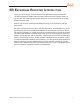
ER Enterprise Reporter Introduction Thank you for choosing to evaluate the 8e6 Technologies ER Enterprise Reporter. The ER is designed to readily obtain information about end users’ Internet activity via log files (text files containing Web access data) from a source device such as the 8e6 R3000 Enterprise Filter. Both SL and HL server models include RAID technology for fault tolerance and high performance. The ER is comprised of the ER server and client application.
About this Document This document is divided into the following sections: • Introduction - This section is comprised of an overview of the ER product and how to use this document • Service Information - This section provides 8e6 Technologies contact information • Preliminary Setup Procedures - This section includes instructions on how to physically set up the ER in your network environment • Install the Server - This section explains how to configure the ER for reporting • Conclusion - This section
Service Information The user should not attempt any maintenance or service on the unit beyond the procedures outlined in this document. Any initial hardware setup problem that cannot be resolved at your internal organization should be referred to an 8e6 Technologies solutions engineer or technical support representative. 8e6 Corporate Headquarters (USA) Local Domestic US International : : : 714.282.6111 1.888.786.7999 +1.714.282.
Preliminary Setup Procedures Unpack the Unit from the Carton Inspect the packaging container for evidence of mishandling during transit. If the packaging container is damaged, photograph it for reference. Carefully unpack the unit from the carton and verify that all accessories are included. Save all packing materials in the event that the unit needs to be returned to 8e6 Technologies.
Select a Site for the Server The server operates reliably within normal office environmental limits. Select a site that meets the following criteria: • Clean and relatively free of excess dust. • Well-ventilated and away from sources of heat, with the ventilating openings on the server kept free of obstructions. • Away from sources of vibration or physical shock.
Rack Mount the Server Rack Setup Precautions Warning: Before rack mounting the server, the physical environment should be set up to safely accommodate the server. Be sure that: • The weight of all units in the rack is evenly distributed. Mounting of the equipment in the rack should be such that a hazardous condition is not achieved due to uneven mechanical loading. • The rack will not tip over when the server is mounted, even when the unit is fully extended from the rack.
Rack Mount Instructions for HL Servers Rack Setup Suggestions • • Determine the placement of each component in the rack before you install the rails. Install the heaviest server components on the bottom of the rack first, and then work up. Identify the Sections of the Rack Rails You should have received two rack rail assemblies with the 8e6 server unit.
Locking Tabs: Both chassis rails have a locking tab, which serves two functions. The first is to lock the server into place when installed and pushed fully into the rack, which is its normal position. Secondly, these tabs also lock the server in place when fully extended from the rack. This prevents the server from coming completely out of the rack when you pull it out for servicing.
Install the Server into the Rack You should now have rails attached to both the chassis and the rack unit. The next step is to install the server chassis into the rack. Do this by lining up the rear of the chassis rails with the front of the rack rails. Slide the chassis rails into the rack rails, keeping the pressure even on both sides (you may have to depress the locking tabs when inserting). When the server has been pushed completely into the rack, you should hear the locking tabs “click.
Install the Server into a Telco Rack If you are installing the 8e6 server unit into a Telco type rack, use two L-shaped brackets on either side of the chassis (four total). First, determine how far follow the server will extend out the front of the rack. A larger chassis should be positioned to balance the weight between front and back. If a bezel is included on your server, remove it.
Rack Mount Instructions for SL Servers Rack Setup Suggestions • • Determine the placement of each component in the rack before you install the rails. Install the heaviest server components on the bottom of the rack first, and then work up. Install the Inner Slides 1. Locate the right inner slide, (the slide that will be used on the right side of chassis when facing the front panel of the chassis). 2.
Install the Slide Assemblies to the Rack 1. After you have installed the short and long brackets to the outer slides, you are ready to install the whole slide assemblies (outer slides with short and long brackets attached) to the rack. (See the previous page.) 2.
Install the Chassis into the Rack 1. Push the inner slides, which are attached to the chassis, into the grooves of the outer slide assemblies that are installed in the rack as shown below: 2.
Install the SL or HL Server Bezel After rack mounting an SL or HL server, the bezel should be installed on the front end of the chassis. NOTE: This portion of the installation process requires you to unpack the bezel. The bezel has been packaged separately from the unit to prevent damage during shipping. A. Hold the bezel upright and facing towards you (Fig. 1). Fig. 1 - Front of bezel B. Note that each end of the bezel contains two raised bumps (Fig. 2). Fig. 2 - Bumps on right end of bezel Fig.
Check the Power Supply This server is equipped with a universal power supply that handles 100-240 V, 50/60 Hz. A standard power cord interface (IEC 950) facilitates power plugs that are suitable for most European, North American, and Pacific Rim countries. Power Supply Precautions Warning: • Use a regulating uninterruptible power supply (UPS) to protect the server from power surges, voltage spikes and to keep the server operating in case of a power failure.
General Safety Information Server Operation and Maintenance Precautions Warning: Observe the following safety precautions during server operation and maintenance: WARNING: If the server is used in a manner not specified by the manufacturer, the protection provided by the server may be impaired. WARNING: 8e6 Technologies is not responsible for regulatory compliance of any server that has been modified.
• Do not expose the server to rain or use near water. If liquids of any kind should leak into the chassis, power down the server, unplug it, and contact 8e6 Technologies technical support. • Disconnect power from the server before cleaning the unit. Do not use liquid or aerosol cleaners. AC Power Cord and Cable Precautions Warning: • The AC power cord for the server must be plugged into a grounded, power outlet.
Motherboard Battery Precautions Caution: The battery on the motherboard should not be replaced without following instructions provided by the manufacturer. Only qualified service personnel should replace batteries. The battery contains energy and, as with all batteries, a malfunction can cause heat, smoke, or fire, release toxic materials, or cause burns. Do not disassemble, puncture, drop, crush, bend, deform, submerge or modify the battery. Do not incinerate or expose to heat above 140°F (60°C).
Install the Server Step 1: Setup Procedures This step requires you to link the workstation to the ER. You have the option of using the text-based Quick Start setup procedures described in Step 1A, the Administrator console setup procedures described in Step 1B, or the LCD panel setup procedures described in Step 1C.
Step 1A: Quick Start Setup Procedures Storage Device Setup (for Attached Storage Units) If you have a NAS (SCSI Connected Storage Device or “SAN”) that will be used with the ER, you will need to connect it to the ER at this point. Refer to the Appendix at the end of this document for instructions on how to connect the SCSI Connected Storage Device. Link the Workstation to the ER Monitor and Keyboard Setup A. Connect the PC monitor and keyboard cables to the rear of the chassis. B. Turn on the PC monitor.
Fig. 3 - Diagram of SL chassis front panel, power button at far right Fig. 4 - Diagram of HL chassis front panel, power button at far right Once the ER is powered up, proceed to the instructions for HyperTerminal Setup Procedures.
HyperTerminal Setup Procedures If using a serial console, follow these procedures to create a HyperTerminal session. A. Launch HyperTerminal by going to Start > Programs > Accessories > Communications > HyperTerminal: B.
C. At the Connect using field, select the COM port assigned to the serial port on the laptop (probably “COM1”), and then click OK to open the Properties dialog box, displaying the Port Settings tab: D. Specify the following session settings: • • • • • Bits per second: 9600 Data bits: 8 Parity: None Stop bits: 1 Flow control: Hardware E.
F. In the HyperTerminal session window, go to File > Properties to open the Properties dialog box, displaying the Connect To and Settings tabs: G. Click the Settings tab, and at the Emulation menu select “VT100”. H. Click OK to close the dialog box, and to go to the login screen. NOTE: If using a HyperTerminal session, the login screen will display with black text on a white background.
Login screen The login screen displays after powering on the ER unit using a monitor and keyboard, or after creating a HyperTerminal session. NOTE: If the screensaver currently displays on your screen, press the Enter key to display the login screen. A. At the login prompt, type in menu. B. Press the Enter key to display the Password prompt. C. At the Password prompt, type in the following: #s3tup#r3k D. Press Enter to display the Quick Start menu screen. Quick Start menu screen A.
Quick Start menu: administration menu A. At the Press the number of your selection prompt, press 2 to select the “Quick Start Setup” process. The Quick Start menu takes you to the following configuration screens to make entries: • • • • • Configure network interface LAN1 Configure default gateway Configure DNS servers Configure host name Time Zone regional setting NOTE: See the Network screens for Network Settings, and Regional Setting in Step 1B for content included in the Quick Start setup screens. B.
System Status screen The System Status screen contains the following information: • • • • • • • • Capturing Interface specified in screen 3 (Configure network interface LAN1) lan1 IP address and netmask specified in screen 3, and current status (“Active” or “Inactive”) Default gateway IP address specified in screen 4 (Configure default gateway) ER host name specified in screen 6 (Configure host name) DNS server IP address(es) specified in screen 5 (Configure DNS servers) Regional timezone setting specifie
Step 1B: Console Setup Procedures Preliminary Setup Create a “setup workstation” using a Windows-based laptop or desktop machine with a network card and Internet Explorer 6.0 (or later). The setup workstation will be used for accessing the ER server on the network and configuring the unit. Workstation Configurations A. From the desktop of the setup workstation, follow the procedures for your machine type: • • • • Windows XP - go to Start > Control Panel. Open Network Connections.
Link the Workstation to the ER The procedures outlined in this sub-section require the use of the CAT-5E crossover cable. A. Plug one end of the CAT-5E crossover cable into the ER’s LAN 1 port. left. NOTE: When facing the rear of the chassis, the LAN 1 port is the port on the Portion of SL chassis rear Portion of HL chassis rear B. Plug the other end of the CAT-5E crossover cable into the setup workstation’s network card.
D. Power on the ER by lowering the bezel and pressing the large button at the right of the front panel (see diagrams below): Diagram of SL chassis front panel, power button at far right Diagram of HL chassis front panel, power button at far right WARNING: The ER is an information database.
Network Setup When the ER is fully booted, you can configure network settings. For this step, you will need your network administrator to provide you the host name, gateway address, and one unused IP addresses. Access the Internet A. Launch Internet Explorer from the setup workstation. B. Type in http://1.2.3.4:88 in the address field. C.
C. Click OK to go to the main screen of the Administrator console: Network Settings A.
B. Enter the Host Name that includes your domain name. For example: er.myserver. com. This must be a valid DNS entry. C. Enter the LAN 1 IP address of the ER server. This IP address must be FTP-accessible via the Web access logging device, and via port 3306 from the client workstation that will run the reports. D. Enter the Netmask (subnet) that will define the traffic designated for the LAN. E.
Regional Setting: Time Zone A. From the Network menu, choose Regional Setting to display the Regional Setting screen in which you specify the geographic region of the ER, select the language set to display in the console, and then select the Network Time Protocol (NTP) servers the ER will use for time synchronization with Internet clocks: B. At the Region pull-down menu, select your country from the available choices. C. At the Location pull-down menu, select the time zone for the specified region. D.
Regional Setting: Language A. If necessary, select a language set from the Language pull-down menu to display that text in the console. B. Click Save. Regional Setting: NTP Servers A. In the Server 1 field on the Time Settings screen, enter the IP address of the primary NTP server you wish to use for clock settings on your server. B. In the Server 2 field, enter the IP address of the secondary NTP server.
Physically Connect the ER to the Network Now that your ER network parameters are set, you can physically connect the unit to your network. This step requires a standard CAT-5E cable (not the CAT-5E crossover cable supplied with the ER). NOTE: This section requires you to restart the ER. If you wish to relocate the ER before connecting it to the network, you must first shut down the server instead of restarting it.
Step 1C: LCD Panel Setup Procedures The ER can be configured using the LCD panel on front of the chassis bezel. When the bezel is placed on the front of the chassis, with the USB plug inserted into the USB port, the default LCD screen displays. To the right of the LCD screen, the keypad displays, consisting of the following keys: up arrow, down arrow, left arrow, right arrow, checkmark, and “X”.
• • • NOTE: Navigation tips in the 8e6 menu: Use the up / down arrow key to scroll up / down the menu Press the checkmark key to choose the current selection Press the “X” to go back to the previous screen Make a selection from the menu, and press the checkmark key to go to that screen. Current Patch Level When the Current Patch Level option is selected, “Enterprise Reporter” and the version number of the currently installed build displays.
A. Choose Change NIC Mode and press the checkmark key to go to the Change NIC Mode screen with the following options: • • Modes Note NOTE: If “Note” is selected, and the right arrow key is pressed, the following message displays: “Remember to reboot the machine for these changes to take effect.” B. Choose Modes, and use the left / right arrow keys to view the available NIC mode selections. C.
Host Name When the Host Name option is selected, the Host Name screen displays with the Configure Hostname menu item. A. Choose Configure Hostname and press the checkmark key to go to the Configure Hostname screen. B. Use the arrow keys to navigate the menu. Press the right arrow key to view the alphabets in first uppercase and then lowercase, numbers from 0-9, and lastly the symbol characters.
Reset Admin Console Password When the Reset Admin Console Password option is selected, the Reset Admin Console screen displays with a WARNING menu item. A. Choose *** WARNING *** to display the message screen: *** WARNING *** The Admin console username/password will be reset to ‘admin’/ ’reporter’ and all locked IPs will be unlocked. B. After reading the warning message, select one of two options on the screen: • • Choose Yes, reset it now! to reset the password and to return to the 8e6 menu.
Heartbeat When the Heartbeat option is selected, the Heartbeat screen displays. A. Press the checkmark or right arrow key three times to view each of the three available options: • • • heartbeat feature enabled (checkbox populated with “x”) heartbeat feature disabled (checkbox empty) check for a heartbeat now (checkbox populated with checkmark, and blinking heartbeat symbol displayed in the line above) B. After making your selection, press the “X” key to return to the previous screen.
Step 2: Change User Name and Password, Set SelfMonitoring Now that the ER is physically installed on your network and you have configured its network settings, you should be able to access the Administrator console. Access the Internet A. Restore the setup workstation you used for the Network Setup to its original settings, and connect it to the network hub to create an “administrator workstation.
If you can access the main screen of the Administrator console, the ER setup is going as planned and you should proceed to changing your User Name and Password. If you cannot access the main screen, verify the following: • • • • • The ER is powered on.
Set Self-Monitoring A. From the Server pull-down menu, choose Self-Monitoring to display the Self Monitoring screen: B. Choose YES to activate monitoring. C. Enter the Master Administrator’s E-Mail Address. D. Click Choice one and enter an e-mail address of an individual in your organization that you would like notified if the ER detects any problems when processing data. This can be the same e-mail address entered in the previous field. Enter up to four e-mail addresses. E. Click Save.
Step 3: R3000 Configuration If you are using 8e6’s R3000 for your Web-access logging device, this step can be performed any time during ER setup, but must be completed in order for the ER to receive logs from the R3000. A. Access the Administrator console of the R3000. B. Choose the Reporting button at the top of the screen to display the Reporting section of the Administrator console. C.
Step 4: Client Workstation Configuration Once your ER is installed, you need to be sure the workstation that will run the client has the following minimum requirements: • • • • • • • • Pentium III class processor or greater 512 MB RAM minimum, 1 GB RAM recommended 1,024 x 768 display 2 GB free hard drive space Windows 2000 or XP, or Macintosh OS X operating system Internet Explorer Version 6.0 or later, Firefox 1.5, or Safari 2.
Step 5: Launch the ER Client A. Launch IE, enter http://x.x.x.x:8080 or https://x.x.x.x:8443 in the address window (in which “x.x.x.x” represents the IP address of the ER server), and then click Go to access the login window of the ER client. B. Enter your Username and Password, and then click LOGIN to access the main screen of the client: NOTE: If you do not have your own Username and Password set up in the ER client, the default Username is manager and the default Password is 8e6ReporT.
C. In the navigation panel, select Settings, and then choose User Permissions from the menu: D. Click Add User to open the Enter User Permissions dialog box: E. Enter the Username. F. Enter the Password, and Confirm Password. G. Select the User Type (“Admin” or “Sub-Admin”). H. Click Save to close the dialog box, and to add the username to the user list. I. Exit the client. You can now launch the client and enter the password you just set up.
Conclusion Congratulations; you have completed the ER quick start procedures. Now that the ER server is set up on your network and the client can be accessed from your workstation, you will need to be sure the Web-access logging device you are using is sending log files to the ER database. Once the ER database is populated, the client can be used for generating reports. Initially, you will only be able to report on IP addresses.
Important Information about using the ER in the Evaluation Mode When evaluating the ER and using this product in the evaluation mode, the Expiration screen in the Administrator console and the ER Server Statistics window in the client will display and function differently than they do in the activated (standard) mode of the ER (described in the ER Administrator User Guide and ER Web Client User Guide).
ER Client, ER Server Statistics Window In the ER Server Statistics window, the note “*Evaluation Mode Enabled” displays above the ER Activity frame. To the right of this note, the Info button displays. When this button is clicked, an alert box opens with the message: “Evaluation Mode – Max Data Storage ‘X’ Weeks” (in which ‘X’ represents the maximum number of weeks in the ER’s data storage scope). Click OK to close the alert box.
LED Indicators and Buttons SL Unit Front LED Indicators and Buttons for Hardware Status Monitoring LED indicators and buttons for hardware status monitoring display on the front panel, located on the right side of the SL and MSA chassis (see diagrams below). LED Indicator Key PWR = Power HD = HDD Activity NIC1 = LAN 1 NIC2 = LAN 2 SL chassis control panel OH = Overheat LED indicators alert you to the status of a feature on the unit while buttons let you perform a function on the unit.
HL Unit Front LED Indicators and Buttons for Hardware Status Monitoring On an HL unit, the following control panel buttons, icons, and LED indicators for hardware status monitoring display on the right side of the front panel: LED Indicator Key PWR = Power HD = HDD Activity NIC1 = LAN 1 NIC2 = LAN 2 OH = Overheat HL chassis control panel UID = Unique IDentifier The buttons and LED indicators for the depicted icons function as follows: UID (button) – On an HL unit, when the UID button is pressed, a steady
Rear LED Indicators for Hardware Status Monitoring UID (LED indicator) – On the rear of the HL chassis, to the left of the power supplies, a steady blue UID LED indicator displays when the UID button on the control panel is pressed. This LED remains lit until the UID button is pressed again. Power Supplies (LED indicators) – The power supplies are located at the right on the rear of the chassis. An LED indicator is located above each of the power plugs.
HL and SL Units Front LED Indicators for Software and Hardware Status Monitoring On an HL or SL unit, the following LED indicators for software and hardware status monitoring display on the left side of the front panel: LED Indicator Key LOG = Log Download Status RAID = Hard Drive Status DB = Database Status UPDT = Software Update Status left side of the front panel LED Indicator Color Condition Description LOG Green On Downloading a log Off No log download detected On RAID mode enabled and run
Regulatory Specifications and Disclaimers Declaration of the Manufacturer or Importer Safety Compliance USA: UL 60950-1 2nd ed.
Electromagnetic Compatibility Class A Notice Industry Canada Equipment Standard for Digital Equipment (ICES-003) Bureau of Standards Metrology and Inspection (BSMI) - Taiwan 58 8e6 Enterprise Reporter Quick Start Guide
EC Declaration of Conformity European Community Directives Requirement (CE) Declaration of Conformity Manufacturer’s Name: 8e6 Technologies Manufacturer’s Address: 828 W.
Appendix: SAN Installation Appendix: SCSI Connected Storage Device This appendix pertains to the installation of the optional NAS (SCSI Connected Storage Device or “SAN”) unit. Preliminary Setup Procedures Unpack the Unit from the Carton Inspect the packaging container for evidence of mishandling during transit. If the packaging container is damaged, photograph it for reference. Carefully unpack the unit from the carton and verify that all accessories are included.
Appendix: SAN Installation Rack Mount the Server Rack Mount Components The following items are needed to install rails for rack mounting: • • 1 x Slide Kit and Mounting Hardware 1 pair Accuride Slide Rails Rack Setup Precautions Warning: Before rack mounting the unit, the physical environment should be set up to safely accommodate the unit. Be sure that: • The weight of all units in the rack is evenly distributed. Hazardous conditions may be created by an uneven weight distribution.
Appendix: SAN Installation Step 1 Remove inner slide rail as shown. Press down on latch to release. Step 2 Attach inner slide rail to chassis using 3 screws as shown. NOTE: When attaching the extended brackets, attach them loosely at first. Adjust the length to fit the cabinet, and then tighten.
Appendix: SAN Installation Step 3 Attach left and right rear (long) extended brackets to the outer rail using 2 screws, 2 washers, and 2 nuts for each bracket. NOTE: Make sure the flange is on the bottom edge. Step 4 Attach left and right front (short) extended brackets to the outer rail using 2 screws, 2 washers, and 2 nuts for each bracket. NOTE: Make sure the flange is on the bottom edge.
Appendix: SAN Installation Step 5 Attach outer rail to chassis using 4 screws and cage nuts per rail, 2 at each end. Step 6 Slide chassis into outer rail carefully, making sure the chassis is level with the slide. NOTE: It’s easier if the drives and power supplies are removed first before sliding the chassis into the outer rail.
Appendix: SAN Installation Install the Unit Link the ER Unit with the SCSI Connected Device This step is a continuation from the Storage Device Setup (for Attached Storage Units) portion of Step 1A or 1B in the ER section. The procedures outlined in this step require the use of the CAT-5E crossover cable and the Ultra SCSI 160 cable. A. Plug the SCSI cable into the upper right slot on the back of the ER unit (see Figure 1, Item A). B.
Appendix: SAN Installation G. Turn on the power switches at the back of the storage device, which are positioned to the right of the power cord connectors. The boot-up process may take up to 5 minutes. When the unit is booted up, the three vertical LED lights at the left of the front panel will be lit up (see Figure 3). Once all LED lights are lit, the ER can be powered on. Shut Down, Restart Procedures Follow the procedures in this section if you need to shut down or restart the storage device.
Appendix: SAN Installation Physical Components 8e6 Enterprise Reporter Quick Start Guide 67
Appendix: SAN Installation LED Display Temperature and Ventilation Status When the LED is green, the blowers are operating at an acceptable RPM, and the internal temperature sensors are within acceptable limits. The LED alternates green and red to indicate a predicted failure of one blower or an alarmingly rapid increase in temperature. If the LED is red, a blower has failed or the unit is too hot, and an audible alarm will sound.
Appendix: SAN Installation Management Alarm A green LED indicates nominal status. A red LED indicates RAID controller or non-PSU/Blower enclosure errors. Silence Button Insert a thin object to temporarily silence the audible alarm. This button also is used for confirming creation in the RAID configuration mode. Disc Drive Alarm The LED is illuminated yellow if a drive is suspected to be bad. Disk Drive Activity The LED is illuminated green when an installed drive is in a “ready” state.
Index B Boot Up 30 BSMI 57, 58 C Change Quick Start password 26 Change User Name and Password 44 crossover cable 4, 19, 29, 36, 60, 65 E EMC 57, 59 ER Client 48 ER Server Statistics 52 Evaluation Mode 2, 51, 52 Expiration 51 F FCC 57 H HL 1, 4, 7, 14, 16, 20, 21, 29, 30, 54, 55, 56, 57, 59 HyperTerminal Setup 21, 22 I ICES-003 57, 58 Install Bezel 14 L LCD Panel 19, 37 Login screen 25 Log in to the Administrator Console 31, 43 LVD 57 N NAS 2, 4, 20, 28, 37, 60 O Overheat 53, 54 P Physically Connect
R R3000 1, 36, 46 Rack Setup Precautions 6 RAID 1, 56, 69 reboot 37, 41 Reset admin console account 26 Reset Admin Console Password 41 Reset system to factory defaults 26 RoHS compliant 59 S SCSI 2, 4, 20, 28, 37, 60, 65 serial port cable 4, 19, 20 shut down 36, 37, 41 SL 1, 4, 11, 14, 20, 21, 29, 30, 53, 56, 57, 59 spare parts kit 4 U UID 54 UL 57 8e6 Enterprise Reporter Quick Start Guide 71
8e6 Corporate Headquarters (USA): 828 West Taft Avenue Orange, CA 92865-4232 • Tel: 714.282.6111 or 888.786.7999 Fax: 714.282.6116 (Sales/Technical Support) • 714.282.6117 (General Office) Satellite Office: 8e6 Taiwan: 7 Fl., No. 1, Sec. 2, Ren-Ai Rd., Taipei 10055, Taiwan, R.O.C.