
Installation Manual


8
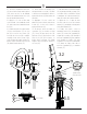
2.4 Atornillar la tuerca de seguridad
(16) para estabilizar todo. Atornillar los
tornillos (19) a su posición final dejando
1/4’’ (6 mm) de espacio entre la tuerca
de seguridad (16) y la arandela de metal
(15).
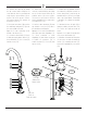
2.5 Introducir el pico (8) en la base del
grifo (10). Apretar el tornillo de fijación
sin mucha fuerza y verificar la fluidez del
movimiento del pico (giro sobre su eje).
Si se dificulta el movimiento, aflojar el
tornillo fijador. Volver a colocar el tornillo
de cabeza plana.
1/4’’ (6 mm)
2.4 Remonter l’écrou (16) pour fixer le
tout. Visser les vis (19) pour sécuriser
en position finale en laissant 1/4’’ (6mm)
d’espace entre la rondelle en métal (15)
et l’écrou (16).
2.5 Réinsérer le bec (8) dans la base
(10). Serrer la vis de réglage sans
trop forcer et vérifier la fluidité du bec
(rotation sur son axe). Si le mouvement
est difficile, déserrer la vis. Replacer le
cache vis.
2.4 Screw up the lock nut (16) to stabilize
eveything. Screw on the screws (19) to
secure in final position while leaving 1/4’’
(6mm) of space in between the lock nut
(16) and the metal washer (15).
2.5 Insert the spout (8) in the faucet
base (10). Tighten the set screw without
too much force and verify the fluidity of
the spout’s movement (rotation on its
axis). If the movement is difficult, loosen
the set screw. Reposition the cap screw.
8
9
19
15
10
8
16
12
14
12
16
15
14
11A
14
15
12
16
19
24
6
20
7
22
22
19
24
24
2.4
2.5
15
16
19