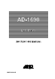
AD-1690 Leak Tester INSTRUCTION MANUAL 1WMPD4002043B
© 2009 A&D Company Ltd. All rights reserved. No part of this publication may be reproduced, transmitted, transcribed, or translated into any language in any form by any means without the written permission of A&D Company Ltd. The contents of this manual and the specifications of the instrument covered by this manual are subject to change for improvement without notice.
CONTENTS 1. INTRODUCTION .......................................................................................................2 1.1. Compliance .........................................................................................................2 2. FEATURES ...............................................................................................................3 3. PART NAMES・CONSTITUTION.............................................................................4 3.1. Main unit...............
1. INTRODUCTION This manual describes how the AD-1690 Leak Tester works and how to get the most out of it in terms of performance. Read this manual thoroughly before using the Leak Tester and keep it at hand for future reference. 1.1. Compliance Compliance with FCC Rules Please note that this equipment generates, uses and can radiate radio frequency energy.
2. FEATURES - This Leak Tester judges a leak by a pressure change, after the initial pressure is set inside the instrument, to a maximum of -20kPa ± 4kPa. The Leak Tester can verify a leak in a small instrument easily (Example: Micro pipette. etc). The amount, -20kPa, attained by evacuating the air with the Leak Tester, is approximately 0.2 atmospheres (based on atmospheric pressure at sea level). (100kPa is approximately 1 atmosphere (based on atmospheric pressure at sea level).
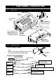
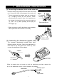
3. 3.1. PART NAMES・CONSTITUTION Main unit Main unit Display AC adaptor jack Plug for accessory adapter opening:right (Connector hole [2]) Keys Plug for accessory adapter opening:left (Connector hole [1]) Air filter unit (Inside:Air filter element) RS-232C interface Main unit bottom side 3.2. Accessories Power supply adapter Note Please confirm that the AC adapter type is correct for your local voltage and receptacle type.
4. CONFIRMING BEFORE USE (1) Confirming the main unit With following state, confirm that the right and left air plugs (○ parts) are pushed in the connector holes firmly. Confirm that the filter unit is installed in the holder located on the main unit bottom side correctly. Main unit bottom side (2) Confirming the operation 1. Connecting the ac adapter to the main unit Open the AC adapter jack cover located on the side of the main unit, insert the AC adapter plug into the AC adapter jack.
After confirming, return the inside pressure of the Leak Tester to atmospheric pressure by removing either the right or left air plug. (If an air plug is not removed, the pressure inside the instrument remains in a state of vacuum.) When not starting another measurement immediately, reconnect the air plugs and close the cover on the AC adapter jack, to avoid dust from invading the main unit.
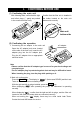
5. MEASUREMENT PREPARATION (1) Connecting the adapter (tube) to the main unit Removing the air plug Remove the air plug located on either side of the main unit. Connect the tube of the adapter to the main unit. * The air plugs and the adapter tube are connected by a coupling having a lock function. When removing the air plug or tube, while pushing on the release ring located on the connector opening (1), pull it out (3) after pushing the air plug or tube lightly (2).
Adapter * When replacing the attachment, remove it by pushing the disconnect button (blue part). 1 2 Disconnect button Attachment (3) Connecting the ac adapter to the main unit Open the AC adapter jack cover located on the side of the main unit, insert the AC adapter plug into the AC adapter jack. Plug the AC adapter into an appropriate electrical outlet. Note - Please confirm that the AC adapter type is correct for your local voltage and receptacle type.
7. MEASUREMENT (1) Power supply Press the ON:OFF key (The display is “display all”). After displaying the setting value (quantity of pressure change and monitor time for leak judgment), the display is“REDY” (that means READY) and is in the measurement standby mode. ON:OFF Quantity of pressure Monitor change All displayed time kPa SEC REDY (2) Starting measurement Connect the test pipette to the tip of the attachment securely. Press START key.
When the pressure, with any leakage does not reach -20kPa or when the quantity of pressure change is over the setting value after reaching -20kPa, the Leak Tester judges that there is a leak and displays “fa1l” (abnormality). When pressing the START key, while in the middle of a measurement, the measurement stops and “5top” is displayed. When pressing the START key again, the Leak Tester judges the measurement result (“pa55”/”fa1l”) after operating the pump again.
8. CHANGING THE JUDGMENT CONDITION Time You can change “quantity of pressure change” and “monitor time” if necessary to set the conditions for judging if there is a leak or no leak. Pressure When canceling the setting halfway, press the ON:OFF key to turn the power supply off. Judgment of leak “fa1l”display Evacuating the air -20kPa (1) Changing the setting value When “ REDY ” *(that means READY) or the measurement result* is displayed, press and hold the SET key (Approx. 2 seconds).
* If the quantity value of pressure change is insufficient when measuring, “fa1l” may be displayed by changing the measurement system pressure (Leak Tester, adapter, attachment). (3) Changing the monitor time The leak tester judges the leak by the monitor time. (Unit: second) Changing the minimum value is by 0.5 seconds. (Factory setting: 3.0 seconds) DOWN Change the value by using the DUPN or DOWN key. * The value displayed with the “○” mark (left side of the display) is the value in memory.
(5) Initializing the setting value When displaying*“ end”of (3), press the DOWN key at once. * Refer to “(3) Changing the monitor time”. SET DOWN After displaying “init”, “init no” is Initialize displayed. confirming display Press SET SET If you want to initialize, press the 1UP1 or DOWN key to change to“ go ” , and press the SET key. After the setting value returns to the value initialized (quantity of pressure change: 0.3kPa, monitor time: 3.
9. FUNCTION Set the function by the following procedure. (1) Entering the function With the power turned off, press and hold the SET key and press the ON:OFF key, to turn the power on. After displaying “5eleCt”, “ re5Ult” (flashing) is displayed. SET press and hold ON:OFF press FUNC (2) Selecting the mode of the function (item) Press the 1UP or DOWN key to select the item of the function.
(4) Setting mode A) Selecting the procedure for measurement result Continued from (3 on page 13) - The 5et procedure is displayed. RESL - Press the 1UP or DOWN key to select either 5et off or 5et on. 5et off:After measurement, Leak Tester display the only judgment result (pa55 or fa1l). 5et on:After measurement, Leak Tester display the final pressure after displaying the judgment result. UP or DOWN SET press RESL Approx. 1 second PASS kPa - Press the SET key to store the setting.
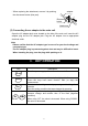
■ Print sample type 0: sample printed with AD-8121B type 1: sample printed with AD-8121B Setting Info. 00.3kPa/03.0s PASS -19.9kPa FAIL -03.5kPa DATE 2010/02/26 TIME 16:31:13 Setting Info. 00.3kPa/03.0s DATE 2010/02/26 TIME 16:31:29 PASS -19.9kPa DATE 2010/02/26 TIME 16:32:08 FAIL -03.5kPa * The date and time of the print sample use the internal clock of the AD-8121B. Set the AD-8121B date and time if necessary. * The AD-1690 can send a special code for printing the date and time.
10. MAINTENANCE AND NOTES (1) Removing the attachment After measurement, remove the pipette and accessory by the following procedure. When storing the main unit, allow of the Leak Tester to equalize to atmospheric pressure. 1. Remove the pipette from the attachment. Pipette 2. Remove the attachment from the adapter. At this time, if the attachment is still connected to a pipette, the inside pressure of the Leak Tester will not return to atmospheric pressure.
3) Main unit Push the cover in the AC adapter jack and push the air plug in the connector hole (right and left side), so that dust can not invade the main unit. 4) Storing the attachment and adapter Store the adapter and attachments in the sealed bag. They will be protected from invading dust.
(3) Exchanging the filter The inside of the main unit is protected from invading dust by the air filter located on the main unit bottom side. Check the main unit regularly, replace the filter element or filter unit if necessary. Turn the power supply of the main unit off by removing the AC adapter. And after returning the inside of the leak tester to atmospheric pressure by removing the pipette, follow this procedure.
3) Installing the filter unit Install the filter unit with the filter element replaced, or with a new filter unit, into the main unit following this procedure: Filter unit 1. Connect the tubes to the both sides 1 of the filter unit. At this time, be careful that the direction of the filter unit is correct (Refer figure 2 at the right). When inserting, do not turn Tube the tube. Holder 2. Install the filter unit into the holder.
11. RS-232C INTERFACE (1) Interface specification The Leak Tester can output the data to an AD-8121B (compact printer: sold separately), AD-1688 (weighing data logger) or a personal computer. etc. This model is a DCE device. Connect the Leak Tester to a personal computer (DTE), using a straight through cable.
(2) Output format - Output of the setting value When turning the power supply on, the present setting information is output. S e t t i n g I n f o . 0 0 . 3 k P a / 0 3 . 0 s CR LF CR LF When changing the setting value, the new setting information is output. S e t t i n g 0 0 . 3 k P a C h a n g / 0 3 . 0 s e d CR CR LF LF - Output of the measurement result When finishing the measurement, the data is output one time.
12.1. Optional accessories and Sold separately Optional accessories - AD-1690-01 Replacement tube set This set consists of the adapter (one piece) and the attachments (one piece each of Large / Medium / Small / Smallest) - AD-1690-02 Replacement filter set This set consists of a filter unit (one piece) and filter elements (ten pieces) - AD-1690-015 Carrying case An optional carrying case for the AD-1690 Leak Tester and AC adapter, with additional space for an AD-1682 Rechargeable battery (sold separately).