Analytical Balance HR-300i HR-202i 1WMPD4000912B
© 2008 A&D Company Ltd. All rights reserved. No part of this publication may be reproduced, transmitted, transcribed, or translated into any language in any form by any means without the written permission of A&D Company Ltd. The contents of this manual and the specifications of the instrument covered by this manual are subject to change for improvement without notice. Windows, Word and Excel are registered trademarks of the Microsoft Corporation.
Contents Basic Operation 1. Introduction ......................................................................................................... 3 1.1. About This Manual .........................................................................................................3 1.2. Features..........................................................................................................................3 1.3. Compliance.................................................................................
Interface And Communication 13. Standard Input and Output Interface ................................................................. 41 13.1. RS-232C Interface....................................................................................................... 41 13.2. Connection to Peripheral Equipment.......................................................................... 42 13.3. Commands ................................................................................................................
1. Introduction This manual describes how the balances of HR-i series work and how to get the most out of them in terms of performance. Read this manual thoroughly before using the balance and keep it at hand for future reference. 1.1. About This Manual This manual consists of the following five parts: Basic operation ............................Describes precautions, the balance's construction and basic operation. Adapting to the environment.........
1.3. Compliance 1.3.1. Compliance With FCC Rules 1.3.2. Compliance With EMC Directives Please note that this equipment generates, uses and can radiate radio frequency energy. This equipment has been tested and has been found to comply with the limits of a Class A computing device pursuant to Subpart J of Part 15 of FCC rules. These rules are designed to provide reasonable protection against interference when equipment is operated in a commercial environment.
5
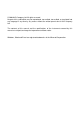
2. Unpacking the Balance Unpack the balance carefully. Keep the packing material to be used for transporting the balance in the future. See the illustrations to confirm that everything is contained. Fine range breeze break ring This ring is an accessory for the HR-202i. Before weighing with a minimum display of 0.01 mg, install this ring in place of the "breeze break ring" to avoid errors caused by drafts.
2.1. Installing the Balance Install the balance as follows: Consider section "3. Precautions " for installing your balance. Place the balance on a solid weighing table. 1 2 Assemble the "Dust Plate", "Breeze Break Ring" and "Weighing Pan" on your balance. There is a reference illustration on the previous page. 3 Leveling foot Adjust the level of the balance using the leveling feet. Ground the balance chassis for discharging static electricity if you have a static problem.
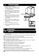
3.2. During Use Note the following items to get accurate weighing data. Metal case Discharge static electricity from the weighing material. Charged material When a weighing sample (plastics, insulator, etc.) could have a static charge, the weight value is influenced. Ground the balance, and Eliminate the static electricity using the optional AD-1683. Try to keep the ambient humidity above 45%RH. Use a metal shield case. Grounding Wipe a charged plastic sample with a damp cloth.
Press the RE-ZERO possible errors. key before each weighing to prevent Calibrate the balance periodically so as to eliminate possible errors. Take into consideration the affect of air buoyancy on a sample when more accuracy is required. Avoid foreign matter (dust, liquid or metal fragments) that could get inside the balance. Operate your balance gently. Shorten the operation time as much as possible ( Opening and closing door, placing and removing a sample).
4. Display Symbols and Key Operation Display Response indicator (Displayed for about 30 seconds when weighing starts.) Processing indicator Units Stabilization indicator Standby indicator of power supply Weighing data or settings Key operation Press and release the key immediately" or "Click the key" ........................................ Press and hold the key ................................................................................................
5. Weighing Units Units 5.1. All weighing units and weighing modes are as follows: Percent mode Counting mode g mg pcs % oz ozt m t tl GN dwt mom ct A unit or mode can be selected and stored in the function table as described in "5.2. Changing the Units". If the law in your area permits, you may use all of the units. You can disable the units that you don't regularly use. And you are able to turn them back on.
5.2. Changing the Units The units or modes can be selected and stored in the function table. The sequence of displaying these can be arranged to fit the frequency of use. The units stored are maintained in non-volatile memory, even if the AC adapter is removed. 1 Press and hold the RANGE key until ba5fnc of the function table is displayed in the weighing mode, then release the key. 2 Press and hold Press the RANGE key several times to display Unit .
5.2.1. Unit setting example The example below sets the units in the order with g (gram) as the first unit followed by pcs (counting mode). 1 Press and hold the RANGE key until ba5fnc of the function table is displayed in the weighing mode, then release the key. Press and hold 2 Press the RANGE key several times to display Unit . 3 Press the PRINT key to enter the unit selection mode. 4 Press the RE-ZERO key to specify the unit of g. The stabilization indicator appears when the unit is specified.
6. Weighing Precautions for the weighing operation Press the RE-ZERO key each time, before placing a sample on the weighing pan, to prevent possible errors. Place a sample in the center of the weighing pan gently. Temperature changes during measurement may cause a weighing error. Shorten the operation time as much as possible. ( Opening and closing door, placing and removing a sample) Use a pair of tweezers to avoid a temperature change due to having your hand in the weighing chamber.
6.2. Dual Range Precision range Standard range Weighing range 0 g to 51 g 51 g to 220 g The HR-202i is equipped with two ranges, "precision range" and "standard range". HR-202i Available minimum display 0.01 mg 0.1 mg 1 mg 0.1 mg 1 mg Precision Range Turn on the balance When weighing is started by pressing the ON:OFF key, the minimum display will be 0.1 mg. Standard Range Turn on the balance Minimum display Minimum display 0.1 mg 0.
6.3. Counting Mode (PCS) This is the mode to determine the number of objects in a sample based on the standard sample unit mass. The unit mass means an average mass of the samples. The smaller the variation in the samples, the more accurate the count will be. The balance is equipped with the Automatic Counting Accuracy Improvement (ACAI) function to improve the counting accuracy. Notes Use samples with a unit mass of 1 mg or more for counting.
Counting mode using the ACAI function The ACAI is a function that improves the accuracy of the unit mass automatically by increasing the number of samples as the counting process proceeds. ACAI: Automatic Counting Accuracy Improvement 8 9 If a few more samples are added, the processing indicator turns on. To prevent an error, add three or more. The processing indicator does not turn on if overloaded. Add the same number of samples as displayed.
6.4. Percent Mode (%) The percent mode displays the weight value in percentage compared to a 100% reference mass and is used for target weighing or checking the sample variance. Selecting the percent mode 1 Press the MODE key to select the unit % (Percent mode). If the percent mode can not be selected, refer to "5. Weighing Units". Storing the 100% reference mass 2 3 4 Press the RANGE key to enter the 100% reference mass storing mode.
7. Response Adjustment This function adjusts the response of the balance and reduces the influence of drafts and/or vibration at the place where the balance is installed. The function has three stages as follows : Response Indicator Parameter Response Stability indicator FAST Cond 0 Fast response, Sensitive value MID. Cond 1 Slow response, Stable value SLOW Cond 2 1 2 Press and hold the MODE key until RESPONSE is displayed, then release the key. Press the MODE key again quickly.
8. Calibration 8.1. Calibration Group Calibration Calibration using a weight that you have Calibration test Calibration test using a target mass Caution Do not allow vibration or drafts to affect the balance during calibration. Calibration test does not perform calibration. To output the data for GLP using the RS-232C interface, set "GLP output (info)" of "Data output (dout)". Refer to "10. Function Table". Calibration test is available only when "GLP output (info)" of "Data output (dout)" is set .
8.2. Calibration Using an External Weight This function calibrates the balance using an external weight. 1 Press and hold Connect the AC adapter and warm up the balance for at least one hour with nothing on the weighing pan. 2 Press and hold the CAL key until Calout is displayed, then release the key. 3 4 5 6 The balance displays Cal 0 . If you want to change the calibration mass, press the RANGE key and proceed to step 4.
8.3. Calibration Test Using an External Weight This function tests the weighing accuracy using an external weight. Calibration test report can be output with "GLP output (info)" (Calibration test does not perform calibration). 1 Press and hold Connect the AC adapter and warm up the balance for at least one hour with nothing on the weighing pan. Release 2 Press and hold the CAL key until CC out is displayed, then release the key. 3 4 The balance displays CC 0 .
9. Function Switch and Initialization 9.1. Permit or Inhibit The balance stores parameters that must not be changed unintentionally (Example: Calibration data for accurate weighing, Data for adapting to the operating environment, Control data for the RS-232C interface). There are two switches for the purpose of protecting parameters. Each switch can select either "permit" or "inhibit". "Inhibit" protects parameters against unintentional operations. 1 Press the ON:OFF key to turn off the display.
9.2. Initializing the Balance This function returns the following parameters to factory settings. Calibration data Function table The sample unit mass value (counting mode), 100% reference mass value (percent mode) External calibration weight and target mass value Function switch settings ("9.1. Permit or Inhibit") Note Be sure to calibrate the balance after initialization. 1 Press the ON:OFF key to turn off the display.
10. Function Table The function table reads or rewrites the parameters that are stored in the balance. These parameters are maintained in non-volatile memory, even if the AC adapter is removed. The function table menu consists of two layers. The first layer is the "Class" and the second layer is the "Item". 10.1. Setting the Function Table Display symbol and keys The symbol "〇" shows effective parameter. When pressing and holding the key in the weighing mode, the mode enters the function table mode.
Setting procedure 1 Press and hold the RANGE key until ba5fnc of the function table is displayed in the weighing mode, then release the key 2 Press the RANGE key to select a class. 3 Press the PRINT key to enter the class 4 Press the RANGE key to select an item. 5 Press the RE-ZERO key to select a parameter for the selected item. 6 If storing parameters of the selected class, press the PRINT key. Then the next class is displayed. If canceling the current operation, press the CAL key.
Setting example This example sets "CR" for "Terminator" and "Output" for "AK, Error code".
10.2.
Class Item and Parameter bp5 Baud rate btpr Data bit, parity bit 5if Serial interface Crlf Terminator type Data format t-Up Timeout erCd AK, Error code Ct5 CTS, RTS control Unit Unit id ID number setting Description 0 1 2 3 4 5 0 1 2 0 1 0 1 2 3 4 5 0 1 0 1 0 1 600 bps 1200 bps 2400 bps 4800 bps 9600 bps 19200 bps 7 bits, even 7 bits, odd 8 bits, none CR LF CR A&D standard format DP format KF format MT format NU format CSV format No limit 1 second No output Output Not used Used CR: ASCII code 0Dh L
10.3. Description of the Class "Environment, Display" Condition ( Cond ) Cond 0 This parameter is for sensitive response to the fluctuation of a mass value. Used for powder target weighing, weighing a very light sample or when quick response weighing is required. After setting, the balance displays FAST. Cond 2 This parameter is for stable weighing with slow response. Used to prevent a mass value from drifting due to vibration or drafts. After setting, the balance displays SLOW.
10.4. Description of the Item "Data Output Mode" The parameter setting of "Data output mode (prt)" applies to the performance when the data is transmitted using the RS-232C interface. Key mode When the PRINT key is pressed with the stabilization indictor turned on, the balance outputs the weighing data and the display blinks one time.
10.5. Description of the Item "Data Format" A&D standard format 5if type 0 This format is used when the peripheral equipment can receive the A&D format. If an AD-8121B is used, set the printer to MODE 1 or 2. This format consists of fifteen characters excluding the terminator. A header of two characters indicates the balance condition. The polarity sign is placed before the data with the leading zeros. If the data is zero, the plus sign is applied.
MT format 5if type 3 A header of two characters indicates the balance condition. The polarity sign is used only for negative data. The weighing data uses spaces in place of the leading zeros. The character length of this format changes dependent upon the unit Header Data Unit Terminator Stable header Unstable header Overload header NU (numerical) format 5if type 4 This format outputs only numerical data. This format consists of ten characters excluding the terminator.
10.6.
Units A&D D.P.
11. ID Number and GLP Report The ID number is used to identify the balance when Good Laboratory Practice (GLP) is used. The ID number is maintained in non-volatile memory even if the AC adapter is removed. The GLP output format is selected at "GLP output (info)" of the function table and can be output to a personal computer or printer using the RS-232C serial interface.
11.2. GLP Report Set the following parameters to output the report. Refer to "13.2. Connection to peripheral equipment", for connection to an AD-8121B. To print the report, set the "GLP output (info)" parameter to "1" and use MODE 3 of the AD-8121B. If MODE1 is used, select temporary dump print mode by pressing the STAT. key of the AD-8121B. To output the report to a personal computer using the RS-232C interface, set the "GLP output (info)" parameter to "2".
Calibration test report using an external weight Note Calibration test does not perform calibration. Key operation 1 Press and hold the CAL key to display CC out and release the key. 2 Cal 0 is displayed. 3 When updating the target value, press the RANGE key and proceed to step 4. When using preset target value, proceed to step 5. 4 Specify calibration mass value using the following keys. RANGE key ........ The key to select the blinking figure RE-ZERO (+)key ..
Title block and end block When mass values are recorded as GLP data, a "Title block" is inserted at the beginning and an "End block" is inserted at the end of a group of mass values in the GLP report. Notes To output the report to an AD-8121B , use MODE 3 of the AD-8121B. If MODE1 is used, select temporary dump print mode by pressing the STAT. key of the AD-8121B. If the data memory function is used (except data 0), the "Title block" and "End block" can not be output.
12. Underhook The underhook can be used for magnetic materials or density measurement. The built-in underhook is revealed by removing the cap on the bottom of the balance. Use the underhook as shown at the lower right. Caution Do not apply excessive force to the underhook. When not in use, attach the cap to prevent dust from getting into the balance. Do not push the underhook upward When turning the balance over, the weighing pan, pan support, breeze break ring and dust plate will fall off.
13. 13.1. Standard Input and Output Interface RS-232C Interface The balance is a DCE device. Connect the balance to a personal computer (DTE) using a straight-through cable.
13.2. Connection to Peripheral Equipment Connection to an AD-8121B printer Preset the following parameters to use the AD-8121B printer.
Connection to a computer and the use of WinCT The balance is of the DCE type (Data Communication Equipment), which can be connected to a personal computer using the RS-232C interface. Before connection, read the personal computer manual thoroughly. Use a standard DCE cable for connection (cable type: straight-through).
13.3. Commands 13.3.1. Command List Note A command has a terminator added, that is specified using "5if Crlf" of the function table, and is sent to the balance. Commands to query weighing data C Cancels the S or SIR command. Q Requests the weighing data immediately. S Requests the weighing data when stabilized. SI Requests the weighing data immediately. SIR Requests the weighing data continuously. Commands to control the balance Same as the CAL key. CAL Turns the display off. OFF Turns the display on.
13.3.2. Acknowledge Code and Error Codes When the "Serial interface function (5if)" parameter is set to "erCd 1", the balance outputs code or error code to each command as follows: (06h) Acknowledge in ASCII code. When the balance receives a command to request data and can not process it, the balance transmits an error code (EC, Exx). When the balance receives a command to request data and can process it, the balance outputs the data.
13.3.5. Command Examples This example uses the "erCd 1" of "5if" so that the (06h) code is output.
Error code This example is of an error using the R command. "erCd 1" is used. The balance transmits an error code when the received command can not be achieved.
Weighing with a tare This example uses "erCd 1" of "5if" so that the (06h) code is output.
Setting a negative target value and filling with a sample until the display becomes zero This example uses "erCd 1" of "5if" so that the (06h) code is output.
14. 14.1. Maintenance Treatment of the Balance Clean the balance with a lint free cloth that is moistened with warm water and a mild detergent. Do not use organic solvents to clean the balance. Do not disassemble the balance. Contact the local A&D dealer if the balance needs service or repair. Use the original packing material for transportation. Consider section "3. Precautions" for using the balance. 14.2.
Display Error code Description Unit mass error The sample unit mass for the counting mode is too light. Storing and using it for counting will cause a counting error. Add samples to reach the specified number and press the PRINT key. Pressing the PRINT key without adding samples will shift the balance to the counting mode. But, for accurate counting, be sure to add samples. Communications error EC,E00 A protocol error occurred in communications. Confirm the format, baud rate and parity.
14.3. Checking the Balance Performance and Environment The balance is a precision instrument. When the operating environment or the operating method is inadequate, correct weighing can not be performed. Place a sample on the pan and remove it, and repeat this several times. If the balance seems to have a problem with repeatability or to perform improperly, check as described below. If improper performance persists after checking, contact the local A&D dealer for repair.
15. Specifications HR-300i Weighing capacity 320 g Maximum display 320.0084 g Minimum display 0.1 mg Repeatability (Standard deviation) 0.2 mg Linearity Stabilization time (Typical at FAST) Sensitivity drift, 10°C to 30°C / 50°F to 86°F Operating environment Percent mode Counting mode Display refresh rate ±0.3 mg Approx. 3.5 seconds ±2 ppm/°C 5°C to 40°C (41°F to 104°F), 85%RH or less (No condensation) 5 times/second or 10 times/second Minimum unit mass 0.
15.1.
15.2. Options and Peripheral Instruments AD-8121B Printer Compact dot-matrix printer Statistical function, clock and calendar function, interval print function, graphic print function, dump print mode 5 x 7 dots, 16 characters per line Print paper (AX-PP143, 45 (W) x 50 (L) mm , ø65 mm) AC adapter or alkaline battery AD-1653 Density Determination Kit Weigh in air x water density = sample density Weigh in water - Weigh in the air Example 10.0000 g x 0.9970 g/cm3 = 21.4 g/cm3 10.0000 g - 9.
AX-USB-9P-EX USB Converter Adds a COM port to a PC. Enables bi-directional communication between the PC and the balance when a USB driver is installed. Can use serial communication software such as WinCT on a PC without COM ports. An RS-232C cable is provided to connect the USB converter to the balance. RS-232C on the HR-i series balance USB serial converter RS-232C cable provided (D-sub 9-pin) AX-T-314A-S External Key Plug This plug produces the same operations as pressing the RE-ZERO and PRINT keys.
Other accessories Order code AD-1682 AD-1684 AD-1685 AD-1689 AD-8526 AD-8920 AD-8922 Name and description Rechargeable Battery This option allows use of the balance in a place where AC power is not available. Electrostatic field meter This option measures the amount of the static charge on the sample, tare or peripheral equipment and displays the result. If those are found to be charged, discharge them using the AD-1683 DC static eliminator.
16. Terms/Index 16.1. Terms Calibration Adjustment of the balance so that it can weigh accurately. Calibration weight A weight used for calibration Data number Numbers assigned sequentially when weighing data or unit weight is stored. Digit The minimum weighing value available. Used for the balance, one digit is the smallest mass that can be displayed.
16.2. % Index Digit ..................................................... 58 dout Data output............................. 28, 31 Dump print ..................................................... 32 -e Weighing pan Error...................... 50 e Overload error.............................. 50 EC,E00 Communications error ................. 51 EC,E01 Undefined command error........... 51 EC,E02 Not ready...................................... 51 EC,E03 Timeout error................................
MEMO 60