AD-4212A/B AD-4212A-100/200/600/1000 AD-4212B-101/102/201/301 Production Weighing Unit INSTRUCTION MANUAL 1WMPD4001448C
© 2009 A&D Company, Limited. All rights reserved. No part of this publication may be reproduced, transmitted, transcribed, or translated into any language in any form by any means without the written permission of A&D Company, Limited. The contents of this manual and the specifications of the instrument covered by this manual are subject to change for improvement without notice. Windows and Excel are registered trademarks of Microsoft Corporation. .
CONTENTS 1. INTRODUCTION...............................................................................................................................4 1-1 Features ............................................................................................................................................... 4 1-2 Compliance .......................................................................................................................................... 5 2. UNPACKING THE BALANCE ..................
10. FUNCTION TABLE ...................................................................................................................... 28 10-1 Structure and Sequence of the Function Table ................................................................................ 28 10-2 Display and Keys .............................................................................................................................. 28 10-3 Details of the Function Table ..................................................
18. COMMANDS.................................................................................................................................68 18-1 Command List .................................................................................................................................. 68 18-2 Acknowledge Code and Error Codes ............................................................................................... 69 18-3 Control Using CTS and RTS ................................................
1. INTRODUCTION This manual describes how the AD-4212A/B series balance works and how to get the most out of it in terms of performance. Read this manual thoroughly before using the balance and keep it at hand for future reference. 1-1 Features Separate Weighing Unit and Display (standard connection cable length 2 m), suitable for building into a production line system. The weighing unit is compact, with a width of 80 mm.
Clock and Calendar Function, adding the time and date to the output data. GLP/GMP Output, using the RS-232C serial interface. Reference Sheet, provided for a quick reference to the balance operation. Windows Communication Tools (WinCT), allows easy communication with a Windows-based personal computer. Windows is a registered trademark of Microsoft Corporation. Multiple Weighing Units, with most of the common units used around the world.
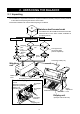
2. UNPACKING THE BALANCE 2-1 Unpacking The balance is a precision instrument. Unpack the balance carefully. Keep the packing material to be used for transporting the balance in the future. See the illustrations to confirm that everything is contained. Stainless steel breeze break Provided for the AD-4212B series balance and the AD-4212-100. For the other models, available as an option (OP-19).
Accessories Calibration weight OIML, Class E2 or equivalent Windows communication tools (WinCT) Model Weight AD-4212A-100 50 g AD-4212B-101/102 AD-4212A-200 100 g AD-4212B-201/301 AD-4212A-600/1000 200 g Mounting fixture (2 pcs.) Screw and washers to attach the mounting fixture (3 sets) AC adapter D-Sub 25-pin connector To mate with the I/O unit. AC adapter ID label Notes About how to attach the mounting fixtures, refer to “26. ATTACHING THE MOUNTING FIXTURES” on page 91.
2-2 Installing the Balance Caution The weighing unit and the display unit were adjusted as a unit. Therefore, make sure that the weighing unit and the display unit have the same serial number. The serial number is printed on the rear of the weighing unit and the display unit. The connection cable also carries the serial number. If the serial numbers of both units are different, the balance may not function properly. When a repair is necessary, submit both the weighing unit and the display unit for repair.
Rear of the weighing unit Arrow mark face up Serial number Make sure the weighing unit, display unit and connection cable have the same serial number. Connection cable Rear of the display unit How to disconnect the cable from the weighing unit Slide the connector sleeve in the direction of the arrow to unlock and gently pull the connector out. Unlocked Slide the connector sleeve in the direction of the arrow 4. Adjust the leveling feet to level the weighing unit.
3. PRECAUTIONS To get the optimum performance from the balance and acquire accurate weighing data, note the following: 3-1 Before Use Install the balance in an environment where the temperature and humidity are not excessive. The best operating temperature is about 20°C / 68°F at about 50% relative humidity. Install the balance where it is not exposed to direct sunlight and it is not affected by heaters or air conditioners. Install the balance where it is free of dust.
3-2 When Building into a System The AD-4212A/B is a precision balance. When it is built into a system and used, errors such as unstable weight values may occur due to static electricity, vibration and materials used for the devices near the balance. When using the balance that is built into a system, take the following precautions. Errors due to a static charge When the ambient humidity is less than 45% RH, insulators such as plastic or glass are prone to static electricity.
When an operator is static charged If an operator’s clothes are static charged, especially in winter, it may be a cause for unstable weight values. Wear an anti-static wrist strap. Errors due to air flow Where the influence of ambient air flow is great such as: close to an air conditioner, door or passage way. Even very subtle air flow that is hard to be detected may influence the weighing operation. Avoid those areas as a weighing site.
Magnetic material The balance uses a strong magnet as part of the balance assembly, so use much care when weighing magnetic materials. Place a non-magnetic object such as aluminum or brass between the sample and the balance, also keep an appropriate distance between them while weighing. 3-3 During Use To minimize the affect by electrical noises, earth ground the weighing unit and the display unit. Make each weighing gently and quickly to avoid errors due to changes in the environmental conditions.
4. DISPLAY SYMBOLS AND KEY OPERATION Key operation Key operation affects how the balance functions.
5. WEIGHING UNITS 5-1 Units With the AD-4212A/B series balance, the following weighing units and weighing modes are available: g mg PC Counting mode Pct OZ OZt ct mm dwt GN TL Percent mode t MS Programmable-unit (AD-4212A only) A unit or mode can be selected and stored in the function table as described in “5-2 Changing the Unit”. If a weighing mode (or unit of weight) has been turned off, that mode or unit will be missing in the sequence.
The table below indicates the weighing capacity and the minimum display for each unit, depending on the balance model. AD-4212A-100 AD-4212A-200 Capacity Minimum Capacity Minimum display display Unit Gram AD-4212A-600 Capacity Minimum display AD-4212A-1000 Capacity Minimum display 110 0.0001 210 0.001 610 0.001 1100 0.001 110000 0.1 210000 1 610000 1 1100000 1 Ounce (Avoir) 3.88 0.000005 7.40 0.00005 21.51 0.00005 38.80 0.00005 Troy Ounce 3.53 0.000005 6.75 0.00005 19.
Unit Gram AD-4212B-102 Capacity Minimum display AD-4212B-201 Capacity Minimum display AD-4212B-301 Capacity Minimum display 110 0.00001 210 0.0001 310 0.0001 110000 0.01 210000 0.1 310000 0.1 Ounce (Avoir) 3.88 0.000001 7.40 0.00001 10.93 0.00001 Troy Ounce 3.53 0.000001 6.75 0.00001 9.96 0.00001 Metric Carat 550 0.0001 1050 0.001 1550 0.001 Momme 29.3 0.00001 56.0 0.0001 82.6 0.0001 Pennyweight 70.7 0.00001 135.0 0.0001 199.3 0.0001 Grain (UK) 1697 0.
6. WEIGHING 6-1 Basic Operation (Gram Mode) 1 Plug in the AC adapter. (Software version display) 2 Press the ON:OFF key to display the weighing mode. (The decimal point position depends on the balance model.) Notes The auto display-ON function is available to display the weighing mode without the key operation when the AC adapter is plugged in. (Function table: ba5fnc p-on) (Display OFF) The function not to tare at start can be selected.
6-2 Smart Range Function The AD-4212B-101 is equipped with two ranges. The precision range has a higher resolution. The standard range has normal resolution. The range switches automatically, depending on the value displayed. Pressing the RE-ZERO key allows weighing in the precision range, regardless of the tare value. The minimum weighing value can be fixed to 0.1 mg or 1 mg by pressing the SAMPLE key. Weighing pan Precision range display 1 Press the RE-ZERO key.
7. CHANGING THE WEIGHING SPEED The weighing speed can be selected from the following three rates to minimize the influence on weighing that is caused by drafts and/or vibration at the place where the balance is installed. Indicator FAST MID. SLOW Parameter Cond 0 Cond 1 Cond 2 Speed Fast Slow Stability Sensitive value Weighing speed indicators Stable value Operation 1 Press and hold the MODE key until RESPONSE is displayed. Press and hold the key And then, press the MODE key again quickly.
8. CALIBRATION Calibration Calibration using the calibration weight Calibration test To check the weighing accuracy, using the calibration weight, and output the result. (Calibration test does not perform calibration.) Caution Calibration adjusts the balance for accurate weighing. Besides periodic calibration and before each use, perform calibration when: • the balance is installed for the first time. • the balance has been moved. • the ambient conditions have changed.
8-1 Calibration This function calibrates the balance using the calibration weight. (Display example: AD-4212B-102) Operation 1 Plug in the AC adapter and warm up the balance with nothing on the pan. • AD-4212A series balance: 30 minutes or more • AD-4212B series balance: one hour or more For the models with a minimum display of 0.1 mg or 0.01 mg, use the stainless steel breeze break provided with the balance for more accurate weighing. 2 Press and hold the CAL key until displayed, then release the key.
From previous page 5 Confirm that there is nothing on the pan and press the PRINT key. The balance measures the zero point. Do not allow vibration or drafts to affect the balance. The balance displays the calibration weight value. 6 Place a calibration weight, of the weight value displayed, on the pan and press the PRINT key. The balance measures the calibration weight. Do not allow vibration or drafts to affect the balance. 7 The balance displays from the pan. end .
8-2 Calibration Test This function tests the balance weighing accuracy using the calibration weight and outputs the result. This is available only when the “GLP output (info)” parameter is set to “1” or “2”. (Calibration test does not perform calibration. Display example: AD-4212B-102) Operation 1 Plug in the AC adapter and warm up the balance with nothing on the pan. • AD-4212A series balance: 30 minutes or more • AD-4212B series balance: one hour or more For the models with a minimum display of 0.
From previous page 5 Confirm that there is nothing on the pan and press the PRINT key. The balance measures the zero point and displays the measured value. Do not allow vibration or drafts to affect the balance. The balance displays the calibration weight value. 6 Place a calibration weight, of the weight value displayed, on the pan and press the PRINT key. The balance measures the calibration weight and displays the measured value. Do not allow vibration or drafts to affect the balance.
9. FUNCTION SWITCH AND INITIALIZATION 9-1 Permit or Inhibit The balance stores parameters that must not be changed unintentionally (e.g. Calibration data for accurate weighing, data for adapting to the operating environment, control data for the RS-232C interface). There are two switches for protecting the parameters. The switches can select either “permit” or “inhibit”. The “inhibit” protects parameters against unintentional operations.
9-2 Initializing the Balance This function returns the following parameters to factory settings. Calibration data Function table Upper/lower limit values The sample unit mass value (counting mode), 100% reference mass value (percent mode) The data that is stored in the balance using the data memory function Calibration weight value Function switch settings Note Be sure to calibrate the balance after initialization. Operation 1 Press the ON:OFF key to turn off the display.
10. FUNCTION TABLE The function table reads or rewrites the parameters that are stored in the balance. These parameters are maintained in non-volatile memory, even if the AC adapter is removed. 10-1 Structure and Sequence of the Function Table The function table menu consists of two layers. The first layer is the “Class” and the second layer is the “Item”. Each item stores a parameter. Example This example sets “Stores weighing data” for “Data memory” and “ 1 minute” for “Interval time”.
10-3 Details of the Function Table Class Item and Parameter Cond Condition 5t-b Stability band width Hold *1 Hold function trc Zero tracking 5pd Display refresh rate ba5fnc Environment pnt Display Decimal point 0 1 0 1 2 3 0 1 0 1 0 Description Fast weighing speed, sensitive value FAST MID. Slow weighing speed, stable value SLOW Stable range is ±1 digit The stabilization indicator illuminates when the display fluctuation is within the range.
Class Cpout Comparator output Item and Parameter Cp-t Comparator output setting Cp Comparator mode Cp fnc Comparator Cp-r *2 Comparison results bep LL buzzer bep_ LO buzzer bepOK buzzer bep HI buzzer bep HH buzzer 0 1 0 1 2 3 4 0 1 0 1 0 1 0 1 0 1 0 1 Cp HH Secondary upper limit Cp Hi Upper limit Cp lo Lower limit Cp ll Secondary lower limit dout Data output Not displayed when BCD output (OP-01) is installed.
Class Item and Parameter ap-p Auto print polarity ap-b Auto print difference data Data memory dout Data output Not displayed when BCD output (OP-01) is installed.
Class Item and Parameter bp5 Baud rate 5if Serial interface Not displayed when BCD output (OP-01) is installed. btpr Data bit, parity bit Crlf Terminator type Data format t-Up Timeout erCd AK, Error code Ct5 CTS, RTS control datp Data polp bcd Polarity 5tbp Stability Displayed only 0erp when BCD OVER output (OP-01) 5trp is installed.
10-4 Description of the Class “Environment, Display” Condition ( Cond ) Cond 0 Cond 2 This parameter is for sensitive response to the fluctuation of a weight value. Used when fast weighing speed is required. After setting, the balance displays FAST. This parameter is for stable weighing with slow response. Used to prevent a weight value drift due to vibration or drafts. After setting, the balance displays SLOW.
Zero tracking ( trc ) This function tracks zero point drift caused by changes in the environment and stabilizes the zero point. Three levels of zero tracking are available. When the weight value is only a few digits, turn the function off for accurate weighing. Note Digit, when used for the AD-4212A/B series balance, indicates the minimum displayable weighing value. trc trc trc trc 0 1 2 3 The tracking function is not used. Used for weighing a very light sample. The tracking function is used.
Tare at start ( p-tr ) When a hopper is attached to the weighing pan and loss-in weighing is performed, the remaining amount of the material will become unknown if tare is performed each time a weighing starts. When "p-tr 0" is selected, tare is not performed at weighing start. So, the remaining amount of the material can be monitored when the power is turned on.
Key mode B When the PRINT key is pressed or the external PRINT contact input is used, the balance outputs or stores the weighing data immediately regardless of the display condition. At this time, the display does not blink. Key mode C When the PRINT key is pressed or the external PRINT contact input is used, with the stabilization indictor on, the balance outputs or stores the weighing data immediately.
DP (Dump print) format 5if type 1 This format is used when the peripheral equipment can not receive the A&D format. If an AD-8121B is used, set the printer to MODE 3. This format consists of sixteen characters excluding the terminator. A header of two characters indicates the balance condition. No overload header is used. The polarity sign is placed before the data, with spaces in place of leading zeros, if the data is not zero or overloaded. The unit, consisting of three characters, follows the data.
5if type 5 CSV format This format separates the data of A&D standard format and the unit by a comma ( , ). This format outputs the unit even when the data is overloaded. When a comma ( , ) is selected for decimal point, separators are set to semicolon ( ; ).
10-8 Data Format Examples Stable Unstable Overload Positive error Overload Negative error Space, Carriage Return, Line Feed Units g ASCII 20h ASCII 0Dh ASCII 0Ah D.P.
10-9 Clock and Calendar Function The balance is equipped with a clock and calendar function. When the “GLP output (info)” parameter is set to “1” or “2” and the “Time/Date output (5-td)” parameter is set to “1”, “2” or “3”, the time and date are added to the output data. Set or confirm the time and date as follows: Operation 1 Press and hold the SAMPLE key until ba5fnc of the function table is displayed, then release the key. 2 Press the SAMPLE key several times to display Cl adj . 3 Press the PRINT key.
Confirming the date 6 The current date is displayed with all the digits blinking. To change the display order of year (y), month (n) and day (d), press the MODE key. The date is output in the order as specified. When the date is correct and the operation is to be finished, press the CAL key and proceed to step 8. When the time is to be confirmed again, press the SAMPLE key and go back to step 4. When the date is not correct and is to be changed, press the RE-ZERO key and proceed to step 7.
10-10 Comparator Function The balance outputs the results of the comparison in three or five levels. AD-4212A series balance: 3-level output (standard) or 5-level output when OP-04 is installed. AD-4212B series balance: 3-level or 5-level output, switched by “Comparator output setting (Cp-t)” of the function table. The comparison results are indicated by HI OK LO on the display and are contact-output from the I/O unit.
Comparison results Display HH HI OK LO LL HH blinking HI illuminated OK illuminated LO illuminated LL blinking Five-level comparison Contact output HI OK HH LO short open open open open open short open open open open open short open open open open open short open LL Buzzer open open open open short * Set the upper limit value equal to or higher than the lower limit value. Set the secondary upper limit value equal to or higher than the upper limit value.
Confirming the upper/lower limit values To confirm the upper/lower limit values during weighing operation, press the MODE key. The upper/lower limit values will be displayed. Even under this condition, weighing operation goes on and data output, contact output of the comparison results and RE-ZERO can be performed.
Note The upper/lower limit values can be confirmed by external commands using the RS-232C serial interface. e.g., Command ?HH (to confirm secondary upper limit value) Response HH, +100.00000 g Command ?HI Response HI +080.00000 Command ?LO Response LO, +060.00000 Command ?LL Response LL, +040.00000 (secondary upper limit value=100.00000 g) (to confirm upper limit value) g (upper limit value=80.00000 g) (to confirm lower limit value) g (lower limit value=60.
11. ID NUMBER AND GLP REPORT The ID number is used to identify the balance when Good Laboratory Practice (GLP) is used. The ID number is maintained in non-volatile memory even if the AC adapter is removed. The GLP output format is selected at “GLP output (info)” of the function table and can be output to a personal computer or printer using the RS-232C serial interface.
11-2 GLP Report Set the following parameters to output the report. To print the report, set the “GLP output ( info )” parameter to “1” and use MODE 3 of the AD-8121B. For details on using the printer, refer to “17-1 Connection to the AD-8121B Printer”. To output the report to a personal computer using the RS-232C interface, set the “GLP output ( info )” parameter to “2”. If the time and date are not correct, set the correct time and date in “Clock ( Cl adj )” of the function table.
Calibration test report using an external weight (Calibration test does not perform calibration.) When the setting is “info 1”: When the setting is “info 2”: General data format AD-8121 format A & D AD4212B-102 01234567 S/N ABCDEFG ID 2000/12/31 D A TE 12:34:56 T I ME CAL.TEST(EXT.) ACTUAL 0.00000 g +50.00020 g TARGET +50.
Title block and end block When weight values are recorded as GLP data, a “Title block” is inserted at the beginning and an “End block” is inserted at the end of a group of weight values in the GLP report. Notes To output the report to an AD-8121B , use MODE 3 of the AD-8121B. If the data memory function is used, the “Title block” and “End block” can not be output. Operation 1 With the weighing data displayed, press and hold the PRINT key until S5tart then release the key. The “Title block” is output.
12. COUNTING MODE (PC) This is the mode to determine the number of objects in a sample based on the standard sample unit mass. The unit mass is the mass of one piece of the sample. The smaller the variables in each sample unit mass are, the more accurate the counting will be. The AD-4212A/B series balance is equipped with the Automatic Counting Accuracy Improvement (ACAI) function to improve the counting accuracy.
Notes If the balance judges that the mass of the samples is too light and is not adequate to be used as the unit mass, it displays 1lo . In that case, store the mass by some quantity. For example, when the model with the minimum weighing value of 0.01 g is used and 10 pieces of samples weigh 0.05 g. Store 100 pieces of samples as 10 and multiply the weighing result by 10.
13. PERCENT MODE (Pct) This is the mode to display the weight value in percentage compared to a 100% reference mass and is used for target weighing or checking the sample variable. Selecting the percent mode 1 Set “Unit selection ( Unit )” parameter of the function table to pct (percent mode). For details, refer to “5-2 Changing the Unit”. Storing the 100% reference mass 2 Press the SAMPLE key to enter the 100% reference mass storing mode.
14. DATA MEMORY Data memory is a function to store weighing data or calibration data to display or output later. The data memory function can also store multiple upper/lower limit values or unit mass values, for later selection as necessary. One of the following data sets can be stored: Weighing data (Up to 200 sets. 100 sets when the time and date are added.
14-2 Memory for Weighing Data The data memory function can store 200 sets of weighing data (100 set if time and date are added). Even if the AC adapter is removed, the data is maintained in non-volatile memory. It is not necessary that the printer or computer be continually connected to the balance, because the balance stores the weighing data in memory.
The following commands can not be used during data storage. Q Query command for weighing data. S Query command for stable weighing data. SI Query command for weighing data. SIR Query command for continuous weighing data.
Transmitting all memory data at one time Confirm that the “Serial interface ( 5if )” parameters are set properly. For details, refer to “10. FUNCTION TABLE” and “17. CONNECTION TO PERIPHERAL EQUIPMENT”. 1 Press and hold the PRINT key until 2 Press the SAMPLE key to display reCall is displayed, then release the key. out . 3 Press the PRINT key to display Sout no 5 Press the RE-ZERO key to display with “no” blinking. out go with “go” blinking.
14-3 Memory for Calibration and Calibration Test Data Calibration data (when and how it is performed) and calibration test data can be stored in memory. All the data in memory is available to be output at one time to a printer or personal computer. Up to 50 data sets of the latest calibration or calibration test can be stored. When the memory capacity has been reached, “fUl” illuminates.
14-4 Memory for Unit Mass in the Counting Mode The data memory function can store 20 sets of unit mass for the counting mode. Even if the AC adapter is removed, the data is maintained in non-volatile memory. Among the 20 sets, “p01” is the memory function for the standard counting mode. The unit mass in memory can be recalled and used for weighing. The unit mass in memory can be recalled and changed. Recalling the unit mass 1 Set the “Data memory ( data )” parameter to “1”.
14-5 Memory for Upper/lower limit values Upper/lower limit values stored in memory can be selected easily by pressing the MODE key. Storage capacity for the 3-level comparison is 20 sets of upper/lower limit values (code numbers C01-C20). "C01" is to store the upper and lower limit values that are set in the function table. The code number appears in the upper left of the display to label the value. Using commands, the upper/lower limit values can be recalled and changed.
Inputting the upper/lower limit values (3-level comparison) 1 Display the weighing mode. Upper/lower limit value code 2 Press and hold the PRINT key until the balance enters the upper/lower limit value selection mode as shown below. Display example The upper limit value of the currently selected code is displayed. 3 Select the code and upper/lower limit values to be used using the following keys.
Switching the upper/lower limit values (3-level comparison) 1 Display the weighing mode. Upper/lower limit value code Weighing mode 2 Press the MODE key to select the upper/lower limit value code. Code C01 Upper limit value Code C01 Lower limit value Code C02 Upper limit value Code C02 Lower limit value 3 Press the PRINT key to return to the weighing mode.
15. PROGRAMMABLE-UNIT (AD-4212A only) This is a programmable unit conversion function. It multiplies the weighing data in grams by an arbitrary coefficient set in the function table and displays the result. The coefficient must be within the range between the minimum and maximum shown below. If the coefficient set is beyond the range, an error is displayed and the balance returns to the coefficient setting mode, prompting to enter an appropriate value. A coefficient of 1 was set at the factory.
16. I/O UNIT SPECIFICATIONS (Standard interface) 16-1 RS-232C/Comparator Contact Output/External Contact Input D-Sub 25 pin numbers D-Sub 25 pin assignments Pin No.
Balance (DCE) Balance interior +5V Personal computer (DTE) example Use a shielded cable. FG 1 (Cable shield) RXD 2 TXD 3 RTS 4 CTS 5 DSR 6 SG 7 Of DOS/V type (D-Sub9) FG Connector shell TXD Pin 3 RXD Pin 2 RTS Pin 7 CTS Pin 8 DSR Pin 6 SG Pin 5 Use a shielded cable.
17. CONNECTION TO PERIPHERAL EQUIPMENT 17-1 Connection to the AD-8121B Printer Set the following parameters to use the AD-8121B printer.
17-2 Connection to a Computer The AD-4212A/B series balance is of the DCE type (Data Communication Equipment), which can be connected to a personal computer using the RS-232C interface. Before connection, read the personal computer manual thoroughly. Use a standard DCE cable for connection (cable type: straight through).
Using the WinCT software, the balance can do the following: 1 Analyzing the weighing data and the statistics with “RsKey” The weighing data can be input directly into an Excel worksheet. Then, Excel can analyze the data to obtain total, average, standard deviation, maximum and minimum value, and display them in a graph.
18. COMMANDS 18-1 Command List Commands to query weighing data C Q S SI SIR Cancels the S or SIR command. Requests the weighing data immediately. Requests the weighing data when stabilized. Requests the weighing data immediately. Requests the weighing data continuously. Commands to control the balance Same as the CAL key. CAL OFF ON P PRT R SMP U HH:∗∗∗. ∗∗∗∗∗ H I :∗∗∗. ∗∗∗∗∗ LO:∗∗∗. ∗∗∗∗∗ LL :∗∗∗. ∗∗∗∗∗ ?HH ?HI ?LO ?LL g g g g Turns the display off. Turns the display on.
18-2 Acknowledge Code and Error Codes When the “Serial interface function ( 5if )” parameter is set to “erCd 1”, the balance outputs code or error code to each command as follows: (06h) Acknowledge in ASCII code. When the balance receives a command to request data and can not process it, the balance transmits an error code (EC, Exx). When the balance receives a command to request data and can process it, the balance outputs the data.
18-3 Control Using CTS and RTS Depending on the “Ct5” parameter of “Serial interface ( 5if )”, the balance performs as follows: Ct5 0 Regardless of whether the balance can receive a command or not, the balance keeps the CTS line HI. The balance outputs data regardless of the condition of the RTS line. Ct5 1 The CTS line is kept Hi normally. When the balance can not receive the next command (e.g. while the balance is processing last command), the balance sets the CTS line to Lo.
19. BCD OUTPUT (OP-01) Weighing data will be output in BCD, in sync with the display refreshing. In addition, the polarity (+/-) and balance condition (stable/not stable, overload(positive/negative)) will be output. The strobe signal allows inputting data easily. Inputting BUSY will hold data or prevent data that is being output from being rewritten. The logic of weighing data, status, and strobe signal can be switched individually in the function table. Contact input is available for RE-ZERO and ON/OFF.
Pin assignments and I/O logic Pin No. 26 27 28 29 39 40 41 42 12 13 14 15 16 17 18 19 20 21 22 23 46 47 48 49 24 25 30 31 32 33 34 35 50 45 44 37 43 1 Housing 5V 10kΩ Output pin assignments Signal 1 2 100 4 8 1 2 101 4 8 1 2 102 4 8 1 2 103 4 8 1 2 104 4 8 1 2 105 4 8 1 2 106 4 8 1 2 107 4 8 Polarity Stability Over Status Strobe Output signal GND Shield 5V 5V 10kΩ 22kΩ Output logic Factory settings • • FG Use a shielded cable.
OP-01 installation procedure 1 Remove the two screws that secure the I/O unit to the rear of the display unit. OP-01 2 Remove the I/O unit and disconnect the two cable connectors. 3 Connect the 14-pin cable connector that was removed in step 2 to the OP-01 connector. 3 5 4 5 4 Leave the 2-pin cable connector as is. 5 Secure the OP-01 board to the rear of the display unit using the two screws.
20. EXTENDED FUNCTIONS (AD-4212A only) The AD-4212A series balance has several extended functions equipped for special applications or to troubleshoot when using the standard functions. Some settings of the extended functions may affect the weighing accuracy. Therefore, they are set to disabled at the factory when shipped. To enable the extended functions, set the function switch "Extended functions" to "1" (To use the extended functions). For details, refer to "9-1 Permit or Inhibit".
75
20-1 Description of "Averaging range" and "Averaging time" Averaging range ( f1-b ) and averaging time ( f1-t ) 1. When the fluctuation of a weight value is beyond the range that is selected in "f1-b", the averaging operation is disabled and the display reflects the varying value. 2. Once the fluctuation becomes within the selected range, the averaging operation starts to stabilize the weight value. 3. The process of averaging increases. When the selected time is reached, moving averaging will be performed.
21. MAINTENANCE Do not disassemble the balance. Contact the local A&D dealer if the balance needs service or repair. Use the original packing material for transportation. Do not use organic solvents to clean the balance. Clean the balance with a lint free cloth that is moistened with warm water and a mild detergent. 22. TROUBLESHOOTING 22-1 Checking the Balance Performance and Environment The balance is a precision instrument.
When the balance is built into a system, remove the balance from the system. Place it on a solid table. Install the breeze break and perform checking. When the balance proper performance is confirmed, refer to page 10 to set up the installation site. Checking that the operating environment or weighing method is proper Operating environment Is the weighing table solid enough Is the balance level? Refer to “3-1 Before Use”.
22-2 Error Codes Display Error code Description Weighing unit connection error The weighing unit is not connected to the display properly. Refer to “2-2 Installing the Balance” to perform a proper connection. Internal error Indicates an internal error as the result of self-check function. (CHECK NO) Repair is required. Contact the local A&D dealer. EC, E11 Stability error The balance can not stabilize due to an environmental problem.
Display Error code Description Unit mass error The sample unit mass for the counting mode is too light. Storing and using it for counting will cause a counting error. Add samples to reach the specified number and press the PRINT key. Pressing the PRINT key without adding samples will shift the balance to the counting mode. But, to acquire accurate weighing, be sure to add samples. Clock battery error The clock backup battery has been depleted. Press any key and set the time and date.
Display Error code EC, E03 Description Timeout error If the timeout parameter is set to “t-Up1”, the balance did not receive the next character of a command within the time limit of one second. Confirm the communication. EC, E04 Excess characters error The balance received excessive characters in a command. Confirm the command. EC, E06 Format error A command includes incorrect data. e.g. The data is numerically incorrect. Confirm the command.
23. SPECIFICATIONS AD-4212A-100 AD-4212A-200 AD-4212A-600 AD-4212A-1000 Weighing capacity 110 g 210 g 610 g 1100 g Maximum display 110.0084 g 210.084 g 610.084 g 1100.084 g Minimum weighing value (1 digit) 0.1 mg 1 mg Repeatability (Standard deviation) 0.15 mg 1 mg Linearity ±0.3 mg ±2 mg ±3 mg Stabilization time in seconds 0-30 g 1.1 0-30 g 0.8 0-30 g 0.9 0-30 g 0.9 (typical at FAST under good 30-110 g 1.3 30-210 g 1.0 30-610 g 1.1 30-1100 g 1.
Weighing capacity Maximum display Minimum weighing value (1 digit) Repeatability (Standard deviation) Linearity Stabilization time (typical at FAST under good environment) Display refresh rate I/O unit RS-232C Comparator contact output External contact input Buzzer Operating environment Calibration weight provided (Conforming to OIML Class E2) Applicable weight values Display Dimensions Weighing pan Mass Dimensions Mass Connection cable AC adapter AD-4212B-201 AD-4212B-301 110 g / 31 g*1 110.
24. DESIGNING A SPECIAL WEIGHING PAN A weighing pan specially designed for the balance can be installed. Design the weighing pan as described below: Using the pan support The pan support can be removed. AD-4212A-100/200 AD-4212B-201/301 Special weighing pan (Example) Weighing pan AD-4212B-101/102 Two points on the center M3 flat head screw: Length 5 mm or less 26 mm Pan support 32.
Using the pan boss The pan boss can not be removed. Approx. 16mm 5 5 Three point M3 screw Length 4 mm or less 7.5mm 19.5mm 30 Approx. 17.8mm Pan support (Can be removed) Front Special weighing pan (Example) Back Weighing unit Weighing unit Pan boss (Can not be removed) Shock absorber specifications The internal shock absorber functions at about 2 kg (as a static force), to protect the mass sensor. A static force of less than 2 kg will not damage the mass sensor.
Mass of the special weighing pan (AD-4212A series balance) Design the weighing pan so that the mass falls in the ranges shown in the table below: AD-4212A-100 Pan support is used (with weighing pan removed) Pan boss is used (with the weighing pan and pan support removed) Pan support is used (with weighing pan removed) Pan boss is used (with the weighing pan and pan support removed) Pan support is used (with weighing pan and pan support plate removed) Pan boss is used (with the weighing pan, pan support pl
AD-4212A-600 When the weighing pan and pan support plate are removed When the weighing pan, pan support plate and pan support are removed 210 g 610 g Mass range to be weighed Mass range to be weighed 210 g 610 g 550 g 510 g 110 g 150 g Mass of special weighing pan Mass of special weighing pan AD-4212A-1000 When the weighing pan and pan support plate are removed When the weighing pan, pan support plate and pan support are removed 210 g 210 g Mass range to be weighed Mass range to be weighed 1
Mass of the special weighing pan (AD-4212B series balance) Design the weighing pan so that the mass falls in the ranges shown in the table below: AD-4212B-101/102 Pan support is used (with weighing pan removed) Pan boss is used (with the weighing pan and pan support removed) AD-4212B-201 Pan support is used (with weighing pan removed) Pan boss is used (with the weighing pan and pan support removed) AD-4212B-301 Pan support is used (with weighing pan and pan support plate removed) Pan boss is used (with the
AD-4212B-201 When the weighing pan is removed When the weighing pan and pan support are removed 110 g 110 g Mass range to be weighed Mass range to be weighed 210 g 210 g 120 g 20 g 160 g Mass of special weighing pan 60 g Mass of special weighing pan AD-4212B-301 When the weighing pan and pan support plate are removed When the weighing pan, pan support plate and pan support are removed 110 g 110 g 310 g Mass range to be weighed 310 g Mass range to be weighed 220 g 20 g 260 g Mass of sp
25. INSTALLING THE DISPLAY UNIT Installing the display unit on a wall using the standard stand 1. Secure the stand, that is attached to the display unit, on the wall using the four screws 2. Adjust the angle of the display unit and tighten the angle adjustment knobs located on both sides of the display unit. Installing in a panel 1. Cut the panel according to the size of the display unit. 2. Remove the angle adjustment knobs located on both sides of the display unit and remove the standard stand. 3.
26. ATTACHING THE MOUNTING FIXTURES The mounting fixtures provided with the AD-4212A/B series balance are used to secure the weighing unit from above in a determined position, when the weighing unit is built into a system. To attach the fixtures to the weighing unit, use the screw holes after the three leveling feet are removed from the bottom of the AD-4212A/B series balance weighing unit. Attachment Procedure 1. Remove the weighing pan, pan support and dust guard. Then, remove the three leveling feet.
27. EXTERNAL DIMENSIONS Display unit Weighing unit (Bottom) Same for all the models 40 9 40 149 115 65 29 59 20 25 107 155 95 176 (239) 237 192 62 (98) Screw part M6XP0.
25 70 230 176 9 AD-4212A-600/1000 80 Height up to the pan boss 87 (82-92) 92.5 (87.5-97.5) 70 * * Adjustable range 62 (98) Weighing unit with the mounting fixtures attached 0.2 249 235 0.4 210 12 62 φ6.5 12 70 10 62 0.
28. OPTIONS AD-8121B Printer Compact thermal dot-matrix printer Statistical function, clock and calendar function, interval print function, graphic print function, dump print mode 5 x 7 dots, 16 characters per line Print paper (AX-PP143, 45 (W) x 50 (L) mm , ø65 mm) AC adapter or alkaline battery.
OP-08: Ethernet interface Used to connect the balance to a LAN. The "WinCT-Plus" data communication software is provided as an accessory and can perform the following. Acquire data from multiple balances connected to a LAN. LAN connection enables reliable data acquisition. Control these balances with commands. Acquire data transmitted from balances. Example: When pressing the PRINT key of the balance, data is output and is acquired by the computer.
29. TERMS/INDEX Terms Stable value Environment The weight data when the stabilization indicator appears. Ambient conditions such as vibration, drafts, temperature, static electricity or magnetic fields which affect the weighing operation. Store To save the weighing data, unit mass, calibration data or upper/lower limit values using the data memory function. Calibration Adjustment of the balance so that it can weigh accurately. Output To output the weighing data using the RS-232C interface.
Cp HH Secondary upper limit...............30 Cp Hi Upper limit ................................30 Cp ll Secondary lower limit ...............30 Cp lo Lower limit ................................30 Cpout Comparator output ....................30 Cp-r Comparison results .............30, 45 Cp-t Comparator output setting ...30, 42 Crlf Terminator .................................32 CSV format ..................................................38 AD-8121B ....................................................
Number of samples................................82, 83 Numerical format .........................................37 -G g5i Capacity indicator ................. 29, 34 GLP report....................................... 21, 46, 47 Gram mode ................................................. 18 -OOK .............................................4, 42, 43 ON/OFF key ...................... 14, 18, 26, 34, 68 OP-01 BCD output/External contact input .........94 RS232C/Five-level comparator contact output..
5-id ID number output................ 31, 38 SLOW ....................................................... 20 5pd Display refresh rate ............. 29, 34 Stability band width ................................ 29, 33 Stability error................................................ 79 Stabilization time.......................... 4, 82, 83, 96 Stable value ........................................... 20, 96 Standard range ...................................... 16, 19 Static charge................................
MEMO 100