AD-4408A Weighing Indicator for PROFIBUS Interface AX-ABCC-PROFI INSTRUCTION MANUAL 1WMPD4001974
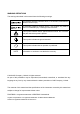
WARNING DEFINITIONS The warnings described in this manual have the following meanings: A potentially hazardous situation which, if not avoided, could result in death or serious injury. A potentially hazardous situation which, if not avoided, may result in minor or moderate injury or damage to the instrument. This symbol indicates caution against electrical shock. Do not touch the part where the symbol is placed. This symbol indicates the ground terminal.
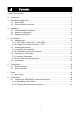
Contents 1. About This Manual ...........................................................................................................2 2. Introduction...................................................................................................................2 3. Description of Each Part ...............................................................................................3 3.1. Status LEDs ................................................................................................
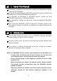
1. About This Manual This manual is intended for those who have a sufficient knowledge about weighing instruments and PROFIBUS. For general information regarding PROFIBUS, specifications, wiring, installation and operation, refer to PROFIBUS-related technical books. For information on PROFIBUS or PROFIBUS products, contact your local PROFIBUS Organization or PROFIBUS distributor. When configuring a network, use cables and connectors designed for PROFIBUS products.
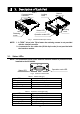
3. Description of Each Part NOTE 2 Communication connector Ground Locking catch Locking catch Status LED NOTE 1 Retaining screw Operation mode LED Fig.1 Interface module part names NOTE: 1. A TORX® driver (size T9) to fasten the retaining screws is not provided with the interface module. 2. A connector for the cable side (D-Sub 9-pin male) is not provided with the interface module. 3.1.
3.2. Communication Connector NOTE: The illustration below shows how the interface module is positioned when installed to the AD-4408A. 6 9 Communication connector 1 5 Fig.3 Connector pin assignment Functions for each pin are as follows. Table 3 Communication connector Pin No.
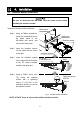
4. Installation 4.1. Interface Module Installation Be sure to disconnect the AD-4408A from the power source before installing the interface module. Install the interface module as follows: Blank panel Step 1 Using a Phillips screwdriver, loosen the screws that secure the blank panel to the AD-4408A rear panel, and remove the blank panel. Step 1 Step 2 Step 2 Insert the interface module into the option slot as shown to the right.
4.2. Network Configuration Turn ON the terminators at both ends of the network. Table 4 Baud rate and distance Baud rate Single line length of cable type A 9.6 kbps 1200 m or less 19.2 kbps 1200 m or less 45.45 kbps 1200 m or less 93.75 kbps 1200 m or less 187.5 kbps 1000 m or less 500 kbps 400 m or less 1.
Step 3 Press the ∧ or ∨ key to select the function group to be set. Display Group name PROFIBUS-related functions pf f Press the ENTER key. The function number will be displayed. Function No. Function Description Default value pf f01 Station No. 0 to 125: Station No. 3 Step 4 Press the ∧ or ∨ key to select the function number to be set. Press the ENTER key. The current setting value will be displayed. Step 5 Change the setting value using either one of the methods below.
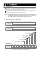
5. PLC Memory 5.1. Address Map Commands to operate the AD-4408A and operating parameters are written into the PLC memory OUT data (6 words) and are executed. Response data from the AD-4408A is read to the PLC memory IN data (10 words). Data used such as Write data is in hexadecimal format. NOTE: The PROFIBUS interface module, when installed into the AD-4408A, uses 12 bytes (OUT) and 20 bytes (IN) of the PLC memory. So, use much care when assigning areas, not to overlap with other slave devices. 5.1.1.
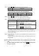
Bit 15 14 13 12 11 10 Fourth word of OUT data 9 8 7 6 5 4 3 2 1 0 5 4 3 2 1 0 Reserved internally Bit 15 14 13 12 11 10 Fifth word of OUT data 9 8 7 6 Command No. Bits 3-15 are internally reserved. Bit 15 14 13 12 11 10 Sixth word of OUT data R / W flag Command request flag Error reset flag 9 8 7 6 5 4 Command bits About OUT Data Write data ----------------------Used by the write command. Command bits-----------------Assigns a function to execute to each bit. Command No.
5.1.2.
Net over Net under Gross over Gross under Input (A/D) over Input (A/D) under Zero error Tare error Net display error Bits 9-15 are internally reserved. Bit 15 14 13 12 11 10 9 Eighth word of IN data 7 6 5 4 3 2 1 0 6 5 4 3 2 1 0 1 0 Status bits Bit 15 14 13 12 11 10 Ninth word of IN data 8 9 8 7 Command No.
Unit Decimal point position 0: None 1: g 2: kg 3: t 4: lb (USA version) 0: None 1: 101 2: 102 3: 103 4: 104 5: 105 123456 12345.6 1234.56 123.456 12.3456 1.23456 About IN Data Slave ready --------------------Bit to turn ON when the AD-4408A is in the weighing mode. Command No. response ---Response data to a command number. Read data ----------------------Response data to a command. R / W response flag----------Response to the OUT data R / W flag. Reserved internally ----------Not used.
5.2. Handling Bits Directly 5.2.1. Handling Command Bits A command bit is in the third word of OUT data. To execute, turn the corresponding command bit ON. The command bit will be effective at the rising edge. The signal level must be maintained for 30 msec minimum. Table 7 Third word of OUT data Command bits Bit 0 Bit 1 Bit 2 Bit 3 Bit 4 Bit 5 Bit 6 Bit 7 Command bit and action Zero Clear the zero value Tare Clear the tare value Hold Net display Gross display Manual print command 5.2.2.
5.3. Operation by Commands 5.3.1. Handling Commands Specify the R / W flag either to the read command or the write command. R / W flag: 0: Write command 1: Read command Specify a command to execute to the command No. Specify the command data to be written to Write data. The command will be effective at the rising edge of the command request flag. The signal level must be maintained for 30 msec minimum. The response result to the command request is output as the command request response flag.
5.4. Commands The master device uses the write command to convey instructions to the AD-4408A. For details, refer to “6.2. Write Command” of “6. Timing Chart”. Table 7 Commands Command No.
6. Timing Chart 6.1. Read Command Specify the data type to read to the command No. The read data is output to the read data area. R / W flag is ON. R / W flag Command No. Command request flag R / W response flag Command No. response Read data Command request response flag Fig.5 6.2. Read command Write Command Write Command Specify the data type to write to the command No. Place the data to be written to Write data. R / W flag is OFF. R / W flag Command No.
Slave Normal Operation Slave normal operation is a signal to confirm that the AD-4408A is connected to the power and is in normal operating conditions. During normal operation, the signal is reversed at a 0.5 to 1 second interval. Slave normal operation 0.5 to 1 sec Fig.7 Slave normal operation signal Error status flag If an AD-4408A error has occurred, the slave ready bit will be turned OFF and the error status flag will be turned ON to convey to the master device that an error has occurred.
7. Errors 7.1. Error Types Error Status Flag This conveys to the master device that an error has occurred. Turn the error reset flag ON to request resetting the error status flag. Table 9 Error status flag Error type Causes Checksum error Program checksum does not match. Input (A/D) error Data can not be acquired from the A/D converter. FRAM error Data can not be written into the FRAM. Calibration error Calibration data is not correct. Mode error Moved to a mode other than the weighing mode.
8. Check Mode 8.1. Checking the PROFIBUS Communication Status 8.1.1. Entering the Check Mode Step 1 While pressing and holding the ENTER key, press the F key. fnc is displayed to indicate that the indicator will enter the general function mode. To go back to the weighing mode, press the ESC key. Step 2 While pressing and holding the ZERO key, press the ENTER key. 1Chc is displayed to indicate that the indicator will enter the check mode. Press the ENTER key again to display an item to be checked.
8.1.2. Checking the Communication Status Press the ∧ or ∨ key to change addresses. Two digits: address (01 to 06, 11 to 1A) Four digits: data (0000 to FFFF) 8 8.