AD-4408A Weighing Indicator for Modbus-RTU Interface AX-ABCC-MODBUS INSTRUCTION MANUAL 1WMPD4001975
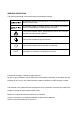
WARNING DEFINITIONS The warnings described in this manual have the following meanings: A potentially hazardous situation which, if not avoided, could result in death or serious injury. A potentially hazardous situation which, if not avoided, may result in minor or moderate injury or damage to the instrument. This symbol indicates caution against electrical shock. Do not touch the part where the symbol is placed. This symbol indicates the ground terminal.
Contents 1. Introduction...................................................................................................................2 2. Description of Each Part ...............................................................................................3 2.1. Status LEDs ........................................................................................................3 2.2. Communication Connector..................................................................................4 3.
1. Introduction The AD-4408A functions as a slave device of Modbus (RTU) when the Modbus-RTU interface module (AX-ABCC-MODBUS) is installed. A signal level can be selected either for RS-232 or RS-485. Data communication using Modbus can be performed by pre-mapped memory operation. Thus, programming communication protocol is not required. NOTE: Memory map and check modes vary with the interface module installed. This manual describes performances when the Modbus-RTU interface module is installed.
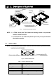
2. Description of Each Part NOTE 2 Communication connector Locking catch Ground Locking catch Device status LED NOTE 1 Retaining screw Communication LED Fig.1 Interface module part names NOTE: 1. A TORX® driver (size T9) to fasten the retaining screws is not provided with the interface module. 2. A connector for the cable side (D-Sub 9-pin male) is not provided with the interface module. 2.1.
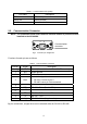
Table 2 Communication LED (COM) LED state 2.2. Description OFF Offline / No power Yellow ON Online (Normal) Red ON Communication error Communication Connector NOTE: The illustration below shows how the interface module is positioned when installed to the AD-4408A. 6 9 Communication connector 1 5 Fig.3 Connector pin assignment Functions for each pin are as follows. Table 3 Communication connector Pin No.
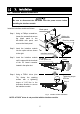
3. Installation 3.1. Interface Module Installation Be sure to disconnect the AD-4408A from the power source before installing the interface module. Install the interface module as follows: Blank panel Step 1 Using a Phillips screwdriver, loosen the screws that secure the blank panel to the AD-4408A rear panel, and remove the blank panel. Step 1 Step 2 Step 2 Insert the interface module into the option slot as shown to the right.
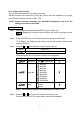
3.2 . Connections and Functions 3.2.1. Cable Connections By connector pin connections, a signal level can be selected either for RS-232 or RS-485. When the signal level is RS-485, add a terminator to both ends of the network. Place a terminator between A and B as shown in the figure below. The A-B terminals of the host device may be reversed, depending on the device type. When the host device has no SG terminal, an SG connection is not necessary.
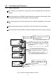
3.2.2. Setting the Functions The functions described here are general functions. General functions are divided into groups per function and are indicated by the group name followed with the function number, FXX. NOTE: General functions determine the AD-4408A performance and all of the settings are stored in the FRAM. Setting Procedure Step 1 While pressing and holding the ENTER key, press the F key. fnc is displayed to indicate that the indicator will enter the general function mode.
Step 5 Change the setting value using either one of the methods below. Method Selecting a parameter Inputting the value Description Only the parameter number to be selected is displayed and blinks. Press the ∧ or ∨ key to select a parameter. All the digits are displayed and a digit to be changed blinks. Press the < or > key to select a digit and press the ∧ or ∨ key to change the value. After setting, press the ENTER key. The next function number is displayed.
4. Modbus Memory 4.1. Memory Map Modbus uses reference numbers and addresses to control the AD-4408A or to read data. The AD-4408A uses Holding Registers and Input Registers. Data types and reference numbers are as shown below. Table 4 Data type Data types Reference No. Description Read and write bit data Output Coil 0 Corresponds to the input of the control I/O. Not used for the AD-4408A. Read only bit data Input Status 1 Corresponds to the output of the control I/O. Not used for the AD-4408A.
Table 6 Input Register (Read only Word data Bit First word of Input Register Input Register memory map Reference No. 3) 15 14 13 12 11 10 9 8 7 6 5 4 3 2 1 0 Unit Decimal point position Setting value Setting value Unit Decimal point position 0: None 123456 1: 101 12345.6 2 2: 10 1234.56 3 3: 10 123.456 4: 104 12.3456 5 5: 10 1.
Zero Clear the zero value Tare Clear the tare value Error reset Hold* Manual print command Net display Gross display Bits 9-15 are internally reserved.
Bit Fifth word of Input Register Bit Sixth word of Input Register Bit Seventh word of Input Register Bit Eighth word of Input Register Bit Ninth word of Input Register Bit Tenth word of Input Register 15 14 13 12 11 10 9 8 7 6 5 4 3 2 1 0 3 2 1 0 3 2 1 0 3 2 1 0 3 2 1 0 3 2 1 0 Net weight Weight value (Low order word) 15 14 13 12 11 10 9 8 7 6 5 4 Net weight Weight value (High order word) 15 14 13 12 11 10 9 8 7 6 5 4 Gross weight Weight value (Low order word) 15 14 13 12 11 10
4.2. Handling Bits Directly 4.2.1. Handling Command Bits A command bit is in the first word of the Holding Register. A command response is in the third word of the Input Register. To execute, turn the corresponding command bit ON. The command bit will be effective at the rising edge. The signal level must be maintained for 30 msec minimum.
5. Timing Chart Slave Normal Operation Slave normal operation is a signal to confirm that the AD-4408A is connected to the power and is in normal operating conditions. During normal operation, the signal is reversed at a 0.5 to 1 second interval. Slave normal operation 0.5 to 1 sec Fig.
6. Errors 6.1. Error Types Error Status Flag This conveys to the master device that an error has occurred. Turn the error reset flag ON to request resetting the error status flag. Table 9 Error status flag Error type Causes Checksum error Program checksum does not match. Input (A/D) error Data can not be acquired from the A/D converter. FRAM error Data can not be written into the FRAM. Calibration error Calibration data is not correct. Mode error Moved to a mode other than the weighing mode.
7. Check Mode 7.1. Checking the Modbus-RTU Communication Status 7.1.1. Entering the Check Mode Step 1 While pressing and holding the ENTER key, press the F key. fnc is displayed to indicate that the indicator will enter the general function mode. To go back to the weighing mode, press the ESC key. Step 2 While pressing and holding the ZERO key, press the ENTER key. 1Chc is displayed to indicate that the indicator will enter the check mode. Press the ENTER key again to display an item to be checked.
Checking the Communication Status Press the ∧ or ∨ key to change addresses. Two digits: address (01, 11 to 1A) Four digits: data (0000 to FFFF) 8 8.
MEMO 18
MEMO 19
MEMO 20