AD-4532B Digital Indicator INSTRUCTION MANUAL 1WMPD4001683
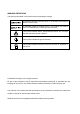
WARNING DEFINITIONS The warnings described in this manual have the following meanings: A potentially hazardous situation which, if not avoided, could result in death or serious injury. A potentially hazardous situation which, if not avoided, may result in minor or moderate injury or damage to the instrument. This symbol indicates caution against electrical shock. Do not touch the part where the symbol is placed. This symbol indicates the ground terminal.
CONTENTS 1. INTRODUCTION .............................................................................................................................3 1-1 Features ............................................................................................................................................. 3 2. PRECAUTIONS ..............................................................................................................................4 2-1 Unpacking..............................................
12. Modbus RTU INTERFACE .........................................................................................................49 12-1 Specifications.................................................................................................................................. 49 12-2 Connection Procedure.................................................................................................................... 52 13. INPUT AND OUTPUT ...........................................................
1. INTRODUCTION Thank you for purchasing the AD-4532B, Digital Indicator. This manual describes how the AD-4532B works and how to get the most out of it in terms of performance. Please read this manual completely before using the AD-4532B. 1-1 Features The AD-4532B has the following features. High-speed conversion A 2000 times-per-second high-speed A/D converter is used for inputs from sensors. A 2000 times-per-second high-speed D/A converter is used for analog outputs.
2. PRECAUTIONS The AD-4532B is a precision instrument. To get the most from your AD-4532B, observe the following precautions. 2-1 Unpacking Unpack the AD-4532B carefully and confirm that everything is contained. Keep the packing material if you want to transport the indicator again in the future. 2-2 Precautions Before Use Avoid water and moisture. Avoid vibration, shock, extremely high temperature and humidity, direct sunlight, dust, and air containing salt or sulfurous gases.
2-3 Precautions During Use The AD-4532B is a precision instrument that measures the microvolt output from sensors. Prevent noise sources such as power lines, radios, electric welders or motors from affecting the instrument. Do not try to modify the AD-4532B. In any hold mode, the hold data is saved in a digital manner, causing no drooping of the value displayed on the display panel or the analog output. Note that the hold function is disabled when the AD-4532B is disconnected from the power supply.
3. SPECIFICATIONS Number of measurement points 1 Sensor type Strain gauge sensors (Output resistance: 10kΩ or less) Sensor power supply (Excitation voltage: To be switched by the function setting.) (1) 5 VDC 350Ω sensor: Up to four sensors can be connected. (1) 2.5 VDC 120Ω sensor: Up to two sensors can be connected. 350Ω sensor: Up to eight sensors can be connected.
Modbus: Modbus RTU Others: Zero adjustment, key disabling function and LATCH function Options AD-4532B-01: BCD parallel output AD-4532B-04: RS-232C serial interface AD-4532B-07: DAV/DAI (analog voltage output/analog current output) AD-4532B-08: Ethernet interface Note: Only one of the options can be installed in the AD-4532B at a time. General specifications Power requirement: 85 VAC to 250 VAC, 50/60 Hz, Approx. 20 VA Operating temperature: -5°C to +40°C Operating humidity: Max.
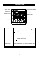
4. FRONT PANEL Standby indicator 5-level comparator indicators Status indicators Main display Stabilization indicator Sub-display (right) Zero indicator Keys Sub-display (left) Main display Displays a measured value or set value. To set the decimal point position, use function mode f-00. Sub-displays Displays an upper limit value (left side) or lower limit value (right side), or displays the set value. Status indicators HI : Turns on when the measured value exceeds the upper limit value (HI).
Keys ESC ON/OFF FNC +/- When this key is pressed for more than three seconds, the display will turn on or off. Even during the display-off state, the power is supplied to the indicator and the standby indicator turns on. Pressing this key in each mode cancels the current state and returns to the previous state. When this key is pressed for more than three seconds, the indicator will enter the function selection mode. This key selects a polarity sign when setting a value.
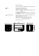
5. REAR PANEL This chapter explains the terminals on the rear panel and how to connect sensors. For the position of each terminal, see the illustration below. (19) (1) Terminal numbers that are printed on the top of the indicator casing Confirm the terminal numbers when making connections When making connections, confirm the terminal numbers printed on the side of the terminal block and on the top of the indicator casing.
5-1-2 Comparator output terminals (31) (32) (33) (34) (31) HI output terminal Outputs HI when the measured value exceeds the upper limit value. (32) OK output terminal Outputs OK when the measured value is as shown below. Lower limit value ≤ measured value ≤ upper limit value (33) LO output terminal Outputs LO when the measured value does not reach the lower limit value.
5-1-4 Modbus RTU terminals (1) - (4) (1) FG terminal Frame ground terminal for Modbus. Connects the Modbus cable shield here. (2) (3) RS-485 terminals A and B terminals for the RS-485, that the Modbus RTU uses. (4) SG terminal Signal ground terminal for the RS-485. 5-1-5 Sensor input terminals (5) - (9), (16) - (18) (5) Sensor power supply + output terminal (EXC+) Positive excitation terminal for the sensors. (6) Remote sensing + input terminal (SEN+) Connects to EXC+ when 4-wire sensors are used.
5-1-6 DAV output terminals (D/A voltage output) (10) - (12) (10) FG terminal Frame ground terminal for the DAV output. Connects the DAV output cable shield here. (11) DAV output terminal DAV output is –10 V to +10 V. Scaling is available by the function setting. (12) DAV output ground terminal 5-1-7 Analog amplifier output terminals (13) - (15) (13) FG terminal Frame ground terminal for the analog amplifier output. Connects the analog amplifier output cable shield here.
6. COMPONENTS AND FUNCTIONS The following flowchart shows how the functions of the AD-4532B are executed.
6-2 Description of Functions 6-2-1 Input filter An analog low pass filter which removes noise in the inputs from the sensors. A pass band can be selected from 3 Hz, 10 Hz, 30 Hz, 100 Hz, 300 Hz and 1 kHz in function mode f-01. 6-2-2 Analog amplifier output The sensor’s analog signals are amplified 625 times and the analog amplifier output (AAO) outputs the amplified signal directly. Therefore, scaling is not available. Output example When the excitation voltage is 5 V and the sensor output is 3.
6-2-7 DAV output The DAV output is the measured value in digital format, converted to an analog output voltage. A DAV output mode can be selected from output without holding or output after holding in function mode f-24. Scaling is available in function modes f-22 and f-23. 6-2-8 BCD parallel output The BCD parallel output is the measured value converted into a BCD format. The output logic can be selected from positive or negative in function mode f-32.
7. CALIBRATION The AD-4532B measures voltage signals from sensors and displays the values. Calibration is performed on the AD-4532B so that it performs correctly. 7-1 Description of Calibration Calibration has the following setting items and operations. Minimum division setting Selects the minimum division. Rated capacity setting Sets the rated capacity. Zero calibration Adjusts the indicator so that the measured value will be zero when no load is applied to the load cell.
7-2 Calibration Modes There are three calibration modes. Digital span mode (d-5p) The sensor’s rated output voltage is keyed in. Calibration is performed without using an actual load. Calibration mode (Cal) Zero and span calibration are carried out using an actual load. Full calibration mode (fCal) Zero and span calibration are carried out using an actual load after minimum division and rated capacity have been set. 7-2-1 Selecting or changing the calibration mode 1.
7-3 Digital Span Mode The sensor’s rated output voltage is keyed in. Calibration is performed without using an actual load. 7-3-1 Setting the minimum division 1. With d-5p displayed, press the ↵ key to go to the digital span mode. 2. When d 01 d-5p is displayed, setting the minimum division is enabled. Use the following keys to set the minimum division. d 01 1∧ Increases the value. 1∨ Decreases the value. 1↵ Saves the minimum division and goes to step 3.
7-3-3 Zero calibration 4. With nothing placed on the load cell, press the 1↵ key. 1↵ Performs zero calibration and goes to step 5. ESC Cancels the operation and returns to the d-5p Cal0 display. d-5p Digital span calibration 7-3-4 Digital span calibration 5. Use the following keys to enter the sensor’s rated output voltage. 6. 1> Selects the digit to set. 1∧ Increases the value. 1∨ Decreases the value. 1↵ Saves the rated output voltage and goes to step 6.
7-4 Calibration Mode Zero and span calibration are carried out using an actual load. 7-4-1 Zero calibration Cal 1. With displayed, press the ↵ key to enter the calibration mode. 2. With nothing placed on the load cell, press the 1↵ Cal key. 1↵ Performs zero calibration and goes to step 3. ESC Cancels the operation and returns to the Cal display. Cal0 Cal -----Cal Cal0 Span calibration 7-4-2 Span calibration 3. Place a weight on the load cell.
7-5 Full Calibration Mode Zero and span calibration are carried out using an actual load after minimum division and rated capacity have been set. 7-5-1 Setting the minimum division 1. With fCal displayed, press the ↵ key to enter the full fCal calibration mode. 2. When d 01 is displayed, setting the minimum division is enabled. Use the following keys to set the minimum division. d 01 fCal 1∧ Increases the value. 1∨ Decreases the value. 1↵ Saves the minimum division and goes to step 3.
7-5-3 Zero calibration 4. With nothing placed on the load cell, press the 1↵ Cal0 key. 1↵ Performs zero calibration and goes to step 5. ESC Cancels the operation and returns to the fCal fCal display. -----fCal Cal0 Span calibration 7-5-4 Span calibration 5. Place a weight on the load cell. Use the following keys to enter the value of the actual weight used. Wait for the value to stabilize and press the 1↵ key. 10000 fCal 5pan 1> Selects the digit to set. 1∧ Increases the value.
8. FUNCTION MODE By selecting the function mode, various functions and data can be set. The set values saved, even if the power is off, are maintained in non-volatile memory. 8-1 Setting a Function 8-1-1 Starting the function mode 1. In the measurement mode, press the FNC key for three seconds or more to enter the function selection mode. Press the 1↵ key to fnc enter the function mode. To select a function item number 8-1-2 Selecting a function item number 2.
8-2 Description of the Function Items Item and Parameter Decimal point f-00 Decimal point position f-01 Input filter Filter f-02 Moving average filter f-03 Digital filter Excitation f-04 voltage Excitation voltage Display f-05 Display update rate Zero f-06 adjustment Zero adjustment range f-07 Stability detection time Stability f-08 Stability detection band f-09 Zero tracking time Zero racking f-10 Zero tracking band f-11 Overflow 0 1 2 3 4 0 1 2 3 4 5 0 | 254 0 | 220 0 1 1 2 4 8 16 32 0 | 100 0 |
Item and Parameter 0000 0 0 0 0 Description 0: Permit 1: Inhibit To permit or inhibit zero adjustment by the ZERO key. To permit or inhibit the hold function by the HOLD key. Keys f-12 Inhibit by key To permit or inhibit monitoring the upper/lower limit values. To permit or inhibit changing the upper/lower limit values. 000 e.g.: 0101 Inhibits zero adjustment by the ZERO key and inhibits monitoring the upper/lower limit values. 0 0 0 0 0: Not available 1: Available To latch the displayed value.
Item and Parameter f-18 COMP ON 0 1 0 1 2 0 | 99 0 f-21 | Hysteresis width 9999 f-22 -20000 Measured value at | 0-V output 20000 f-23 -20000 Measured value at | 10-V output 20000 0 f-24 DAV mode 1 f-19 Comparator Hysteresis mode (continued) f-20 Hysteresis time DAV f-25 Baud rate f-26 Data bit length Modbus f-27 Parity f-28 Stop bit f-29 f-30 Address 1200 2400 4800 9600 19200 38400 7 8 0 1 2 1 2 0 | 99 Description COMP ON by control input is not required.
Item and Parameter Description f-31 f-32 BCD output logic BCD DAV DAI RS-232C Ethernet Reserved internally 0 Positive 1 Negative 0 1 time/s 1 10 times/s f-33 2 100 times/s BCD output rate 3 1000 times/s 4 2000 times/s 5 In sync with the display f-34 -20000 Sets the measured value that corresponds to DAV/DAI Measured value at | output value of 0V/4mA. 0V/4mA output 20000 0 : Factory setting f-35 -20000 Sets the measured value that corresponds to DAV/DAI Measured value at | output value of 10V/20mA.
9. HOLD FUNCTION The AD-4532B has four hold modes; sample hold, peak hold, bottom hold and bipolar peak hold. A hold mode can be selected in function mode f-14. 9-1 Basic Operation 9-1-1 Starting a hold mode Four methods to start a hold mode are available. Using the HOLD key Pressing the HOLD key will start the hold function and display the held value. Pressing the HOLD key again will stop the hold function and display the measured value.
9-2 Hold Modes 9-2-1 Sample hold mode Holds the display and output when receiving the hold input. Sensor input Displayed value Front panel ON OFF HOLD key During the holding operation, HOLD turns on. Rear panel External hold input ON OFF 9-2-2 Peak hold mode Holds the peak value when receiving the hold input. Sensor input Displayed value Front panel ON OFF HOLD key During the holding operation, PEAK and HOLD turns on.
9-2-3 Bottom hold mode Holds the bottom value when receiving the hold input. Sensor input Displayed value Front panel Rear panel ON OFF HOLD key External hold input During the holding operation, ON OFF PEAK and HOLD turn on. 9-2-4 Bipolar peak hold mode Holds the absolute peak value when receiving the hold input. Sensor input Displayed value Front panel ON OFF HOLD key During the holding operation, PEAK and HOLD turn on.
10. COMPARATOR FUNCTION The AD-4532B has two comparator modes; simple comparator and 2D (Two dimensional) comparator. A comparator mode can be selected in function mode f-16. f-17 to f-21 are also comparator-related function modes. The comparator function compares the measured value against the set value and outputs the comparison results (HI, OK or LO) from the rear panel comparator output terminals.
10-1-2 Setting the upper and lower limit values 1. In the measurement mode, press the HI key or LO key to check the upper limit value or lower limit value. 2. In the main display, Hi or lo 4532 1000 400 HI appears. And in the right side of Hi the sub-display, the upper limit or lower limit value that is currently set appears. 1> Switches between the upper limit and lower limit value. 1↵ Selects the item to be changed and goes to step 3.
10-1-3 Example of the simple comparator mode Example: f-16 2 (Continuous comparison, excluding the zero band) Upper limit Lower limit Zero band COMP ON ON OFF HI output ON OFF OK output ON OFF LO output ON OFF COMP ON input and output HI, OK or LO output is available only when the COMP ON input terminal is ON (when the COMP ON input terminal is connected to the IN COM terminal). When the COMP ON input terminal is OFF, no comparison nor result output is performed.
10-2 2D Comparator Mode The 2D (Two dimensional) comparator mode performs a two dimensional comparison by switching the 5-level comparator with the upper and lower limit values that are preset for each level. 10-2-1 Switching the comparator Two switching methods are available. By COMP 1 to COMP 5 inputs (f-16 4 or 5) Switching is performed by the change in position. Connect the position detection switch to the COMP 1 to COMP 5 input terminals. Set function mode f-16 (Comparator mode) to “4” or “ 5”.
10-3 2D Comparator Mode (By COMP 1 to 5 inputs) 10-3-1 Setting the upper and lower limit values for each level 4532 1. In the measurement mode, press the HI key or LO key to check the 1000 upper limit value or lower limit value. 400 LO 2. In the main display, Hi 1 or lo 1 appears. And in the right side lo 1 of the sub-display, the upper limit or lower limit value that is currently set for the level appears. The corresponding z indicator turns on.
10-3-2 Example of the 2D comparator mode (By COMP 1 to 5 inputs) Example: f-16 5 (5-level continuous comparison) When the judgment result is OK: Hi 5 lo 5 Hi 3 lo 3 Hi 2 Hi 4 lo 4 lo 2 Hi 1 lo 1 ON OFF ON OFF ON OFF ON OFF ON OFF ON OFF ON OFF ON OFF ON OFF COMP ON COMP 1 COMP 2 COMP 3 COMP 4 COMP 5 HI output OK output LO output 37
When the judgment result is NG: Hi 5 Hi 3 Hi 2 lo 3 lo 5 Hi 4 lo 4 lo 2 Hi 1 lo 1 ON OFF ON OFF ON OFF ON OFF ON OFF ON OFF ON OFF ON OFF ON OFF COMP ON COMP 1 COMP 2 COMP 3 COMP 4 COMP 5 HI output OK output LO output 38
10-4 2D Comparator Mode (By time control) 10-4-1 Setting the upper and lower limit values for each level 1. In the measurement mode, press the HI key or LO key to check the upper limit value or lower limit value. 2. In the main display, Hi 1 or lo 1 4532 1000 HI appears. And in the right side Hi 1 of the sub-display, the upper limit or lower limit value that is currently set for the level appears. The corresponding z indicator turns on. ti 5t indicates the starting time.
10-4-2 Example of the 2D comparator mode (By time control) Example: f-16 7 (5-level continuous comparison) with the starting and ending time for each level that are set as below.
When the judgment result is NG: Hi 5 lo 5 Hi 3 lo 3 Hi 4 Hi 2 lo 4 lo 2 Hi 1 lo 1 ON OFF COMP ON 0 100 200 300 400 500 600 700 800 900 1000 1100 1200 1300 1400 ms HI output ON OFF OK output ON OFF LO output ON OFF 41
10-5 2D Comparator Mode (Additional Explanation) While the conventional comparison method detects and judges the maximum or minimum value only during measurement, the 2D comparator mode uses contact inputs from the rear panel terminals or elapsed time to make a comparison at various levels. This type of comparison is useful for an operation such that the pressure increases rapidly at the pressurization starting time and changes in pressure occur during the pressurization process.
10-6 Comparator Hysteresis Function A hysteresis width and time is provided for the output relay on/off timing to prevent the output terminals from chattering. When the measured value exceeds the set value, the relay is turned on. If the measured value falls below the set value and it is further reduced by the hysteresis width, or if the hysteresis time has elapsed, the relay is turned off. The hysteresis mode, time and width can be set in function modes f-19, f-20 and f-21.
10-6-2 Upper/lower limit judgment (f-19 1) Relation between OK and HI When the measured value exceeds the set upper limit value, HI is output. Even if the measured value falls below the upper limit value after that, OK is not output immediately. OK will be output when the measured value is reduced by the hysteresis width, or when the hysteresis time has elapsed. Relation between OK and LO When the measured value falls below the set lower limit value, LO is output.
10-6-3 Downward 2-level judgment (f-19 2) Relation between OK and HI Even if the measured value exceeds the set upper limit value, HI is not output immediately. HI will be output when the measured value is increased by the hysteresis width, or when the hysteresis time has elapsed. When the measured value falls below the upper limit value, OK is output immediately. Relation between OK and LO When the measured value falls below the set lower limit value, LO is output.
11. ANALOG OUTPUT The AD-4532B has two types of analog output; the analog amplifier output (AAO) that amplifies the sensor’s analog signals and outputs the amplified signal, and the digital to analog voltage output (DAV) that processes the measured values from the sensors according to the values set in function mode, and outputs the processed signal as a voltage after D/A conversion.
11-2 Digital to Analog Voltage Output (DAV) Processes the measured values from the sensors according to the values set in function modes f-22 to f-24, and outputs the processed signal as a voltage after D/A conversion. The output voltage range is from –10 V to +10 V. Scaling is available in function modes f-22 and f-23. 11-2-1 Specifications Rated output range –10 V to +10 V (Non-inductive load of 5 kΩ or more) Maximum output range –11.0 V to +11.
3 . When dav 0v is displayed, adjusting 0V is enabled. In the right side of the sub-display, the internal correction factor for the DAV output appears. dav 0v valUe 32768 Use the following keys to adjust the output voltage while looking at dav 0v the digital multimeter. 1> Switches among 0 V, 10 V and –10 V. 1∧ Increases the output voltage value. valUe 32496 Also increases the correction factor. 1∨ When kept pressed, increases the correction factor by ten.
12. Modbus RTU INTERFACE The Modbus RTU interface reads the measured values or status from the AD-4532B, or writes the settings to the AD-4532B. Using the Modbus RTU interface, a personal computer, PLC or programmable display can be connected to the AD-4532B. 12-1 Specifications 12-1-1 Specifications Communications protocol Modbus RTU Transmission system RS-485 Transmission distance 1.
12-1-2 Data address Data type Coil 0XXXX Input status IXXXX Input register 3XXXX Address 1 2 3 4 5 1 2 3 4 5 6 7 8 9 10 11 12 13 14 15 16 17 18 19 20 21 22 23 1 2 3, 4 5, 6 Data Hold Release hold Zero Clear zero Save settings in EEPROM Hold Stable Zero band Rated capacity overflow AD conversion overflow HI output LO output OK output Level 1 HI output Level 1 LO output Level 1 OK output Level 2 HI output Level 2 LO output Level 2 OK output Level 3 HI output Level 3 LO output Level 3 OK output Level 4 HI
Data type Holding register 4XXXX Address 1, 2 3, 4 5, 6 7, 8 9, 10 11, 12 13, 14 15, 16 17, 18 19, 20 21, 22 23, 24 25, 26 27, 28 29, 30 31, 32 33, 34 35, 36 37, 38 39, 40 41, 42 43, 44 45, 46 47, 48 49, 50 51 52 53 54 55 Data Upper limit Lower limit Level 1 upper limit Level 1 lower limit Level 2 upper limit Level 2 lower limit Level 3 upper limit Level 3 lower limit Level 4 upper limit Level 4 lower limit Level 5 upper limit Level 5 lower limit Level 1 starting time Level 1 ending time Level 2 starting
12-2 Connection Procedure 12-2-1 When making a connection between a master device and one indicator A device such as PLC Programmable display AD-4532B A A 2 B B 3 Termination resistor Master Slave Use a shielded twisted pair cable to make a connection. Connect termination resistors without fail. (100Ω to 120Ω, 1/2 W to 2 W) The positions of A and B may be reversed for some master devices. If communication can not be enabled after connection, check all of the connections.
13. INPUT AND OUTPUT The AD-4532B has nine input terminals and three output terminals. 13-1 Input Terminal Equivalent circuit diagram VCC +5 V Toggle switch Mechanical relay contact 19 to 26 28 Approx.4 mA AD-4532B interior 30 Mechanical contact (Switch) Semiconductor contact (Transistor open collector) タ TTL open collector output Note on connecting input terminals Ensure to allow 5 ms or more for both the mechanical contact ON time and OFF time.
13-2 Output Terminal Equivalent circuit diagram Non-polar MOS FET relay 31 to 33 Load AC power supply Varistor AD-4532B interior Contact rating 31 to 33 250 VAC 0.1 A 30 VDC Load 0.5 A DC power supply 34 Spark killer AD-4532B interior Note on connecting output terminals Use a load within the specified rating to prevent over-voltage or over-current from destroying the MOS FET relay. Connect a spark killer to the load appropriate to AC/DC. Do not short-circuit the load.
14. CHECK MODE The AD-4532B has check modes to check the performance of input and output terminals as follows. Display check mode, analog output check mode, I/O check mode and key check mode. 14-1 Check Mode Procedure 14-1-1 Entering a check mode 1. In the measurement mode, press the FNC key for three seconds or more to enter the function selection mode. 4532 1000 400 FNC 3 seconds 2. Press the > key several times to display CHeCk (Check mode). 3.
14-1-4 Excitation voltage check mode 6. Press the 1↵ key to check the excitation voltage supplied to the sensor from the AD-4532B. In the example display shown to the right, the excitation voltage is 5 V Press the 1↵ 1> 5. key to go to the DAV voltage check mode dav. Moves to the next check mode without performing the current check mode ESC Returns to the CHeCk 5 CHeCk volt display. 14-1-5 DAV voltage check mode dav 7. The DAV voltage check mode checks the D/A output voltage.
14-1-7 Span calibration mV/V value check mode 10. The span calibration mV/V value check mode displays the mV/V value at span calibration. Press the 1↵ 5pan key to check the span calibration mV /V value. In the example display shown to the right, the value at span calibration is 2.18372 mV/V Press the 1↵ 1> 2.18372. 2.18372 te5t. key to go to the I/O check mode Moves to the next check mode without performing the CHeCk 5pan current check mode ESC Returns to the CHeCk display.
14-1-9 Key check mode 13. The key check mode checks the front panel keys. 1> key Moves to the initialization mode without performing the current check mode 1↵ Enters the key check mode and goes to step 14. ESC Returns to the CHeCk key display. 14. When each key is pressed, the corresponding digit in the sub-displays turns to “1”.
14-1-10 Initialization 15. Initialization restores the various settings to the factory setting values. 1> init Moves to the display check mode without performing the initialization. 1↵ Enters the initialization mode and displays init f in the main display. ESC Returns to the 16. Using the 1> CHeCk init f CHeCk init display. key, select an item to be initialized. In the example display shown to the right, initialization of the calibration settings is init C selected.
15. OPTIONS The AD-4532B has the following options available: AD-4532B-01 BCD parallel output AD-4532B-04 RS-232C serial interface AD-4532B-07 DAV/DAI analog voltage output/analog current output AD-4532B-08 Ethernet interface Only one of the options can be installed in the AD-4532B at a time. 15-1 AD-4532B-01 BCD Parallel Output The BCD parallel output is an interface to convert measured values into a BCD format and output.
15-1-2 Equivalent circuit diagram A1 to A16, A18, B1 to B16 pin output terminals A19, B19 pin common terminals +5V B18 pin HOLD input terminal AD-4532B interior 15-1-3 Connector pin assignment Pin No.
15-2 AD-4532B-04 RS-232C Serial Interface The RS-232C serial interface can be connected to a device such as a personal computer, PLC or a programmable display, to output the values displayed by the AD-4532B and perform controlling, collection or recoding.
15-2-4 Command format When a command is processed, the indicator transmits the received command or the data. If a command can not be processed, for example, when the indicator is in operation, the indicator transmits “I”. Communication errors may occur due to external noise. When the indicator receives an undefined command, it transmits “?”. Command to request data Outputs the displayed data immediately after receiving the command. Command: R Command example: R CR LF Response example W T , ± 0 1 2 .
Command to send the upper/lower limit values Outputs the set upper and lower limit values including the values of the 2D comparator mode. Command: S, Sx (Where x is the comparator level of the 2D comparator mode. For example, S1 means the setting value for the level 1.) Command example: S CR LF S 1 CR LF Response example S , ± 0 1 2 . 3 4 5 , ± 0 1 2 . 3 4 5 CR ± 0 1 2 . 3 4 5 , ± 0 1 2 .
15-3 AD-4532B-07 Analog Voltage/Current Output (DAV/DAI) The DAV/DAI analog voltage/current output is an interface to output the values displayed by the AD-4532B as an analog voltage or analog current. The analog output range for voltage is from –10 V to +10 V and for current, from 4 mA to 20 mA. An analog voltage output from -10 V to +10 V or analog current output from 4 mA to 20 mA can be obtained according to the values set in function modes f-34 and f-35.
15-3-2 Fine adjustment of zero and span Note on using this function Use this mode only when adequate accuracy can not be obtained by the regular scaling set in function modes f-34 and f-35. This mode uses the internal correction factor and requires a high-precision digital multimeter. If a low-precision multimeter is used, it may adversely affect the indicator performance and the output voltage accuracy.
15-3-3 DAV/DAI voltage/current check This mode allows the user to check the DAV/DAI value. To use this mode, first enter the check mode. Voltage is used for checking. To check the current value (DAI), the displayed value of 0 corresponds to 4 mA and the value of 10 corresponds to 20 mA. No negative values are available for the DAI values and the increase of the displayed value by one corresponds to the increase of the current value by 1.6 mA.
15-4 AD-4532B-08 Ethernet Interface The Ethernet interface allows communication between the AD-4532B and a personal computer. The Windows Communication Tools for Ethernet, WinCT-Plus is provided with this option. The data format and commands are the same as those of the AD-4532-04 RS-232C serial interface. 15-4-1 Features External view Using this option, one personal computer can collect data from multiple indicators. Using this option, commands from a personal computer can control the indicators.